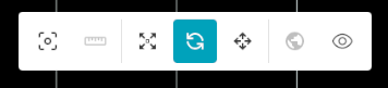
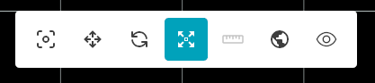
Editor bar
Roads
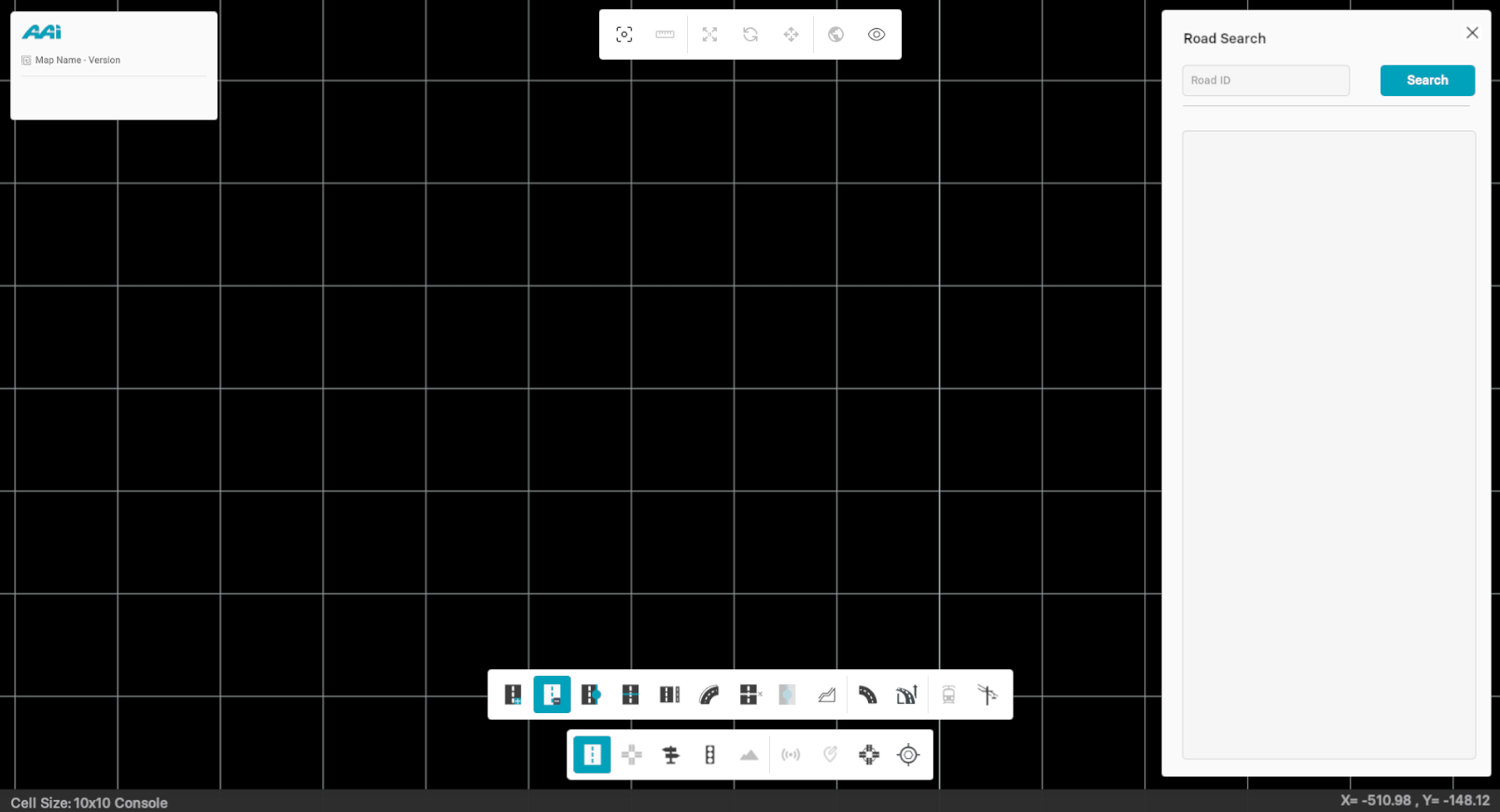
The Toolbar provides you a variety of options while creating a map in the window.
Create Road
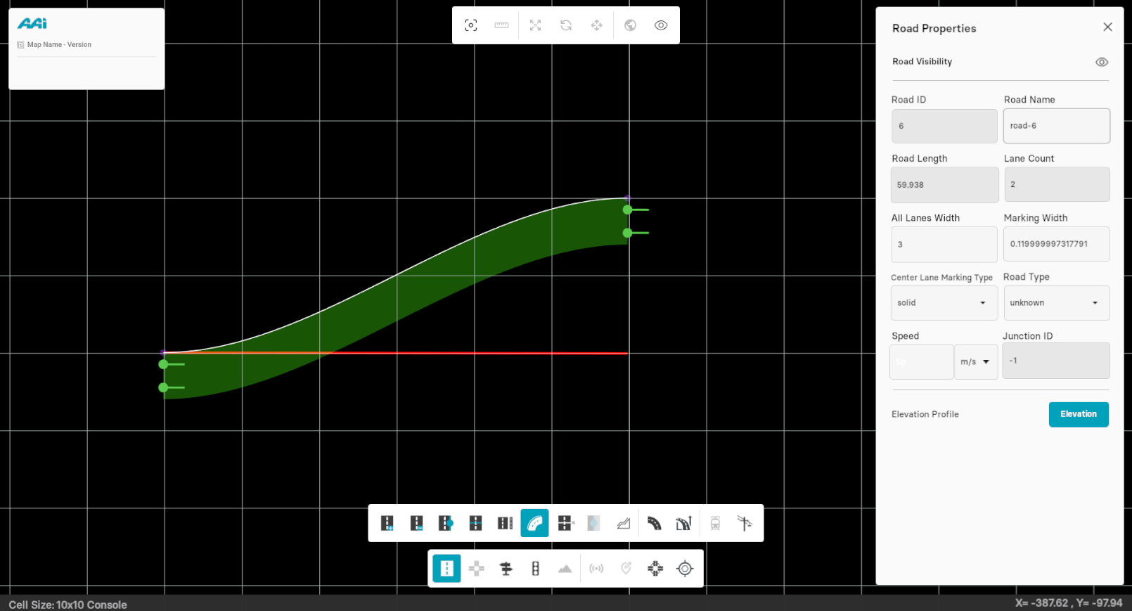
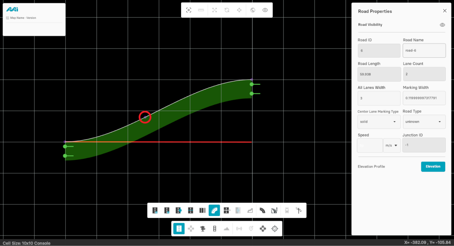
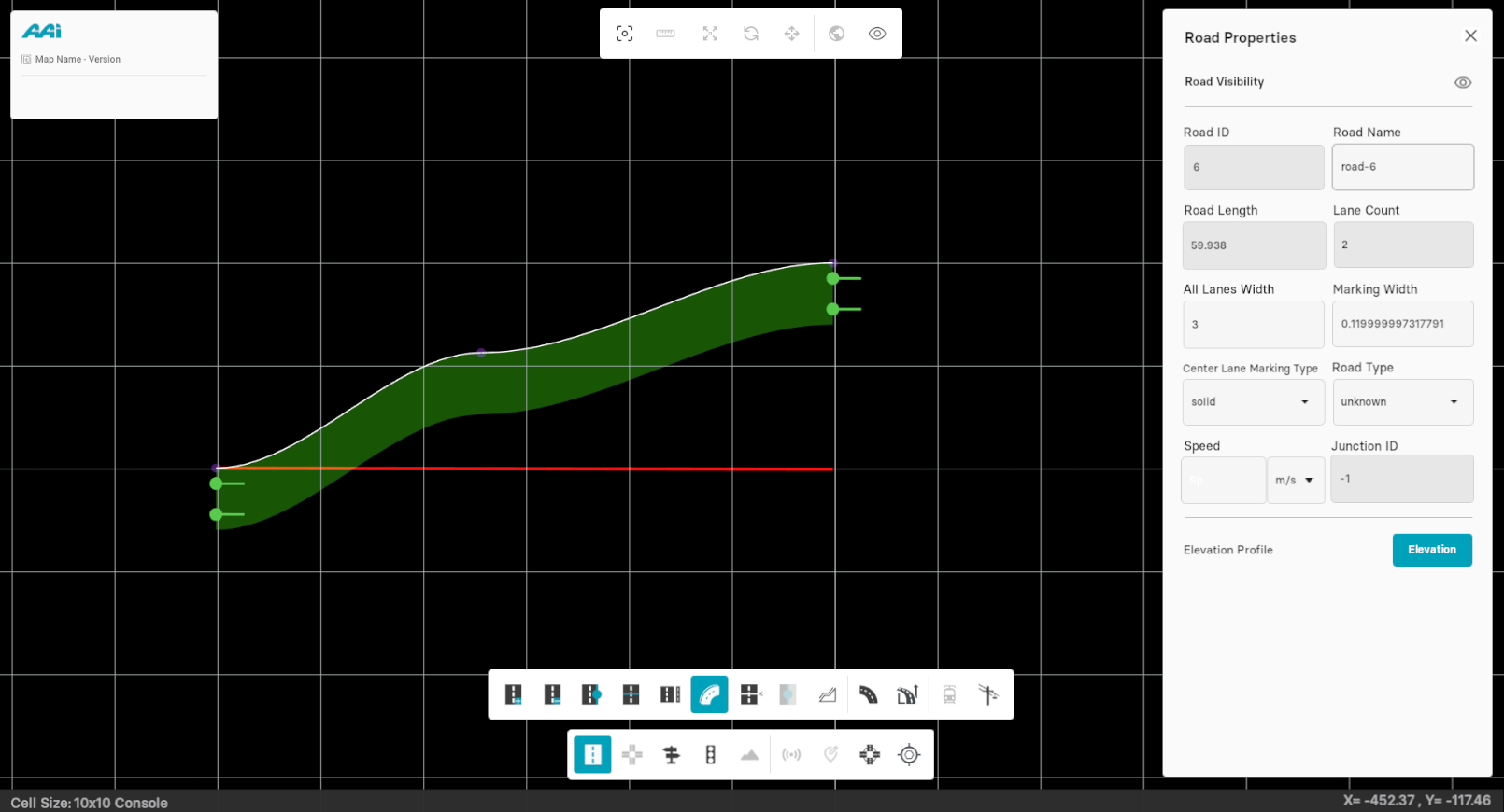
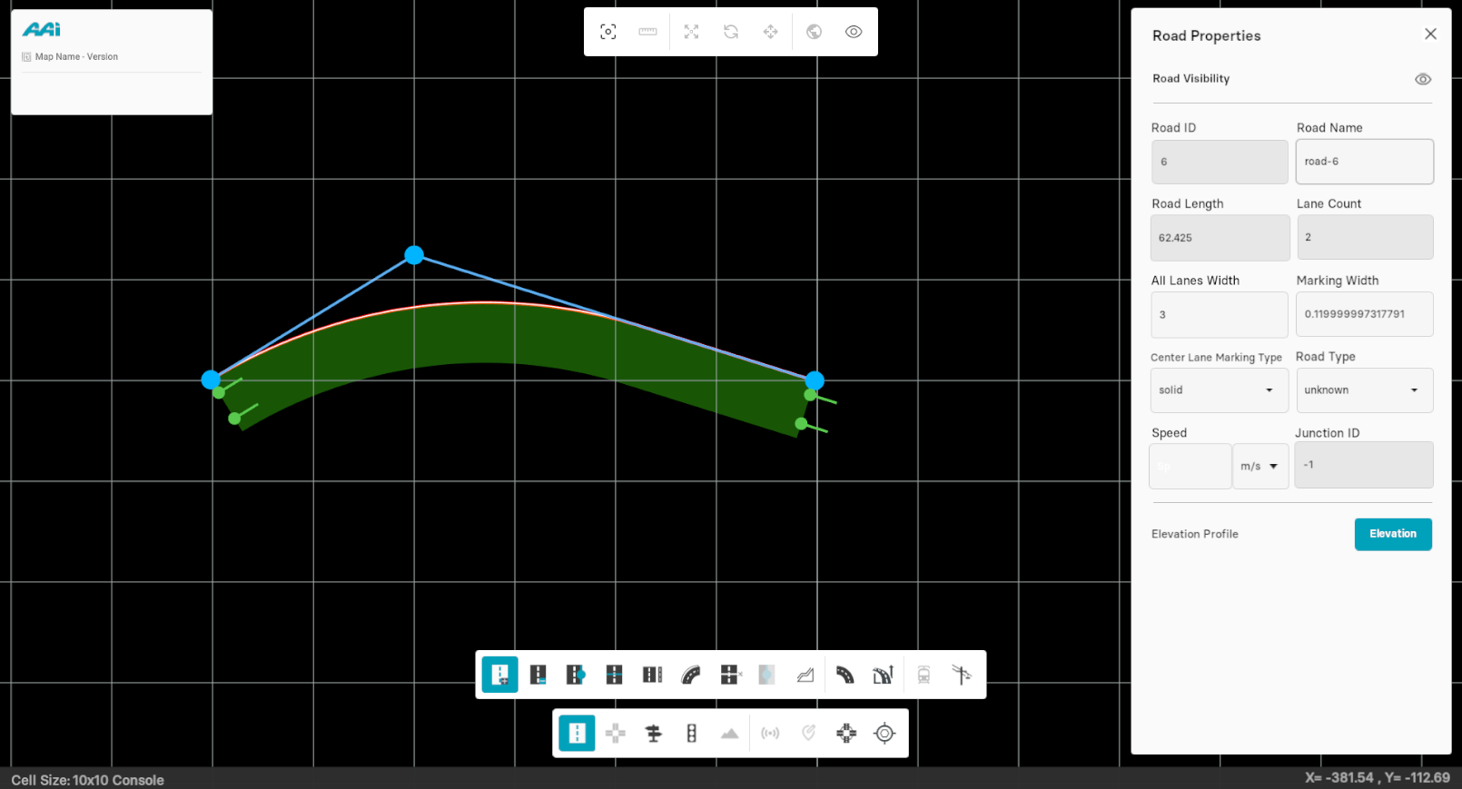
This tool lets the user draw a road in your map. All roads consist of a reference line which defines its basic geometry. This reference line requires an initial and a final point on the grid window defined by the user.
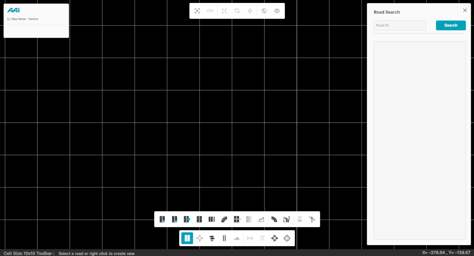
1. Select the "Create Road" sub-tool inside of the "Road Edit" tool. Click the secondary-mouse button (usually right) within the RepliMap window to set the initial coordinates of the road.
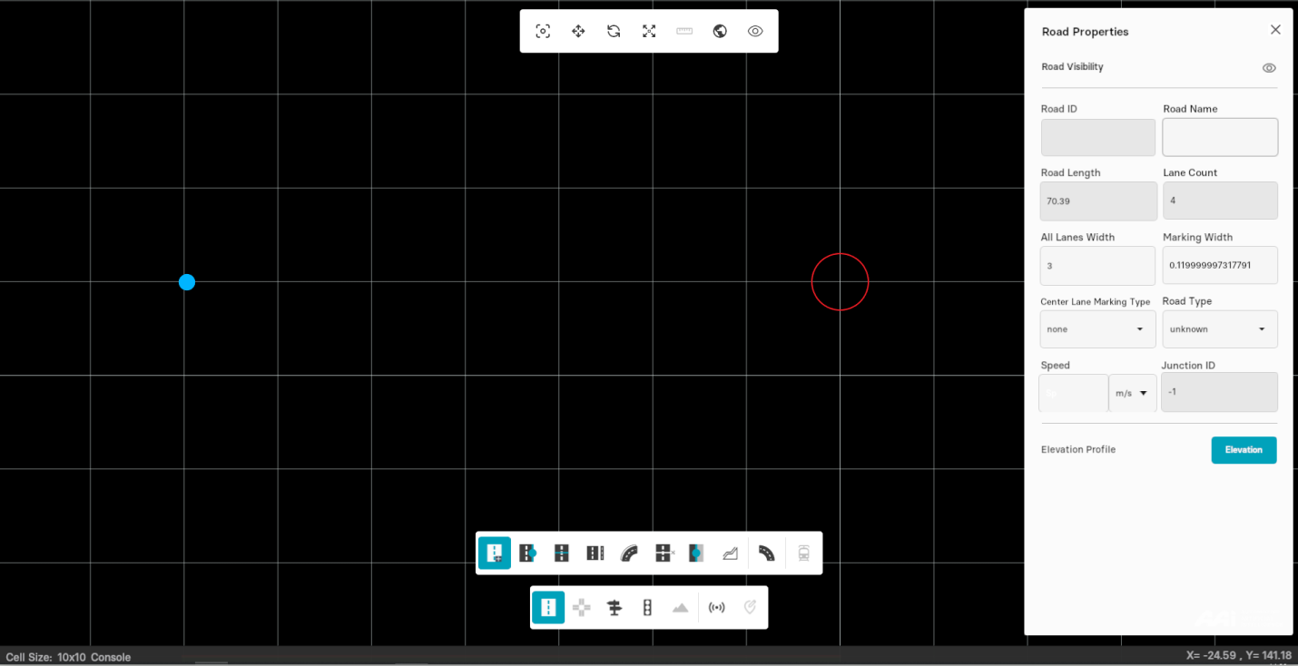
2. Press the secondary-mouse button (usually right) at a different position for the end location of the road.

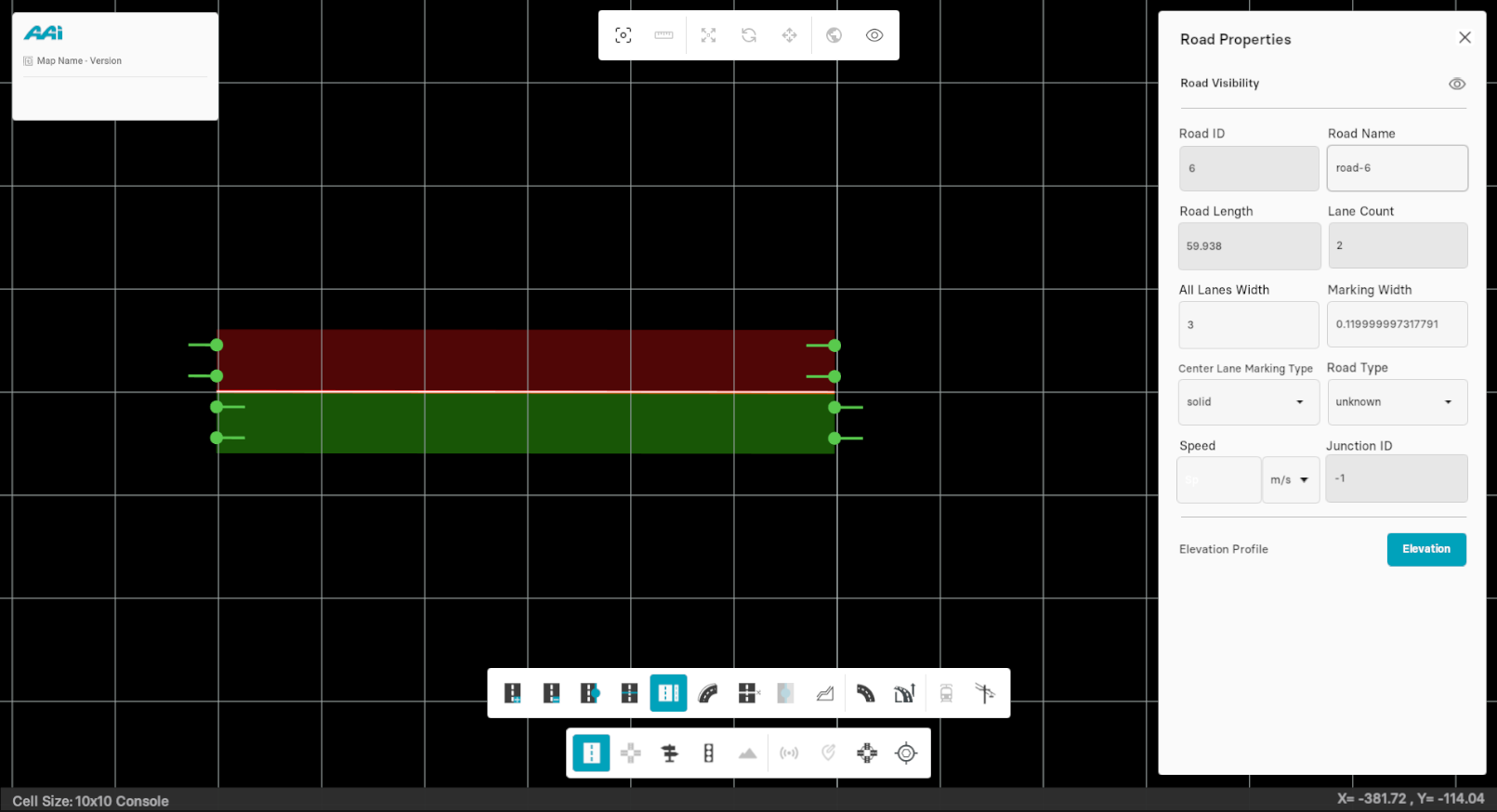
Once you click the points consecutively, a road is automatically laid out between them. On the right side of the window, you"ll find all the road features displayed. These parameters can be adjusted as needed.
For more details about these parameters, click here
Delete Road
This sub-tool allows the user to delete any existing road within the window. There are, however, two ways in which you can delete a road:
- Directly through the Delete Road sub-tool
- Through the del shortcut
Approach #1: Through the "Delete Road" tool
1. Select the "Delete Road" sub-tool inside of the "Road Edit" tool.
2. Press the 'Del' key on your keyboard. This will delete the selected road
Approach #2: Through the "del" shortcut
1. Select the road by using the "Road Edit" tool.
2. Press the "del" key in your keyboard. This should cause the selected road to be deleted.
Cut Road
This sub-tool allows you to split up the existing road into two or more sections.
1. Select the 'Cut Road' sub-tool within the 'Road Edit' tool.

2. Press the road with the primary-mouse button (usually left) in the area you want to make the split.

Road Visibility
Hide Road
This tool allows the user to temporarily remove a road from the visible map display without deleting it. When selected, the user can click on any existing road within the grid window to hide it from view. The road's geometry and associated data remain intact and can be re-displayed later. This is useful for decluttering the map or focusing on other elements during editing.
1. Click the desired road with the primary (usually left) mouse button to open its properties panel.
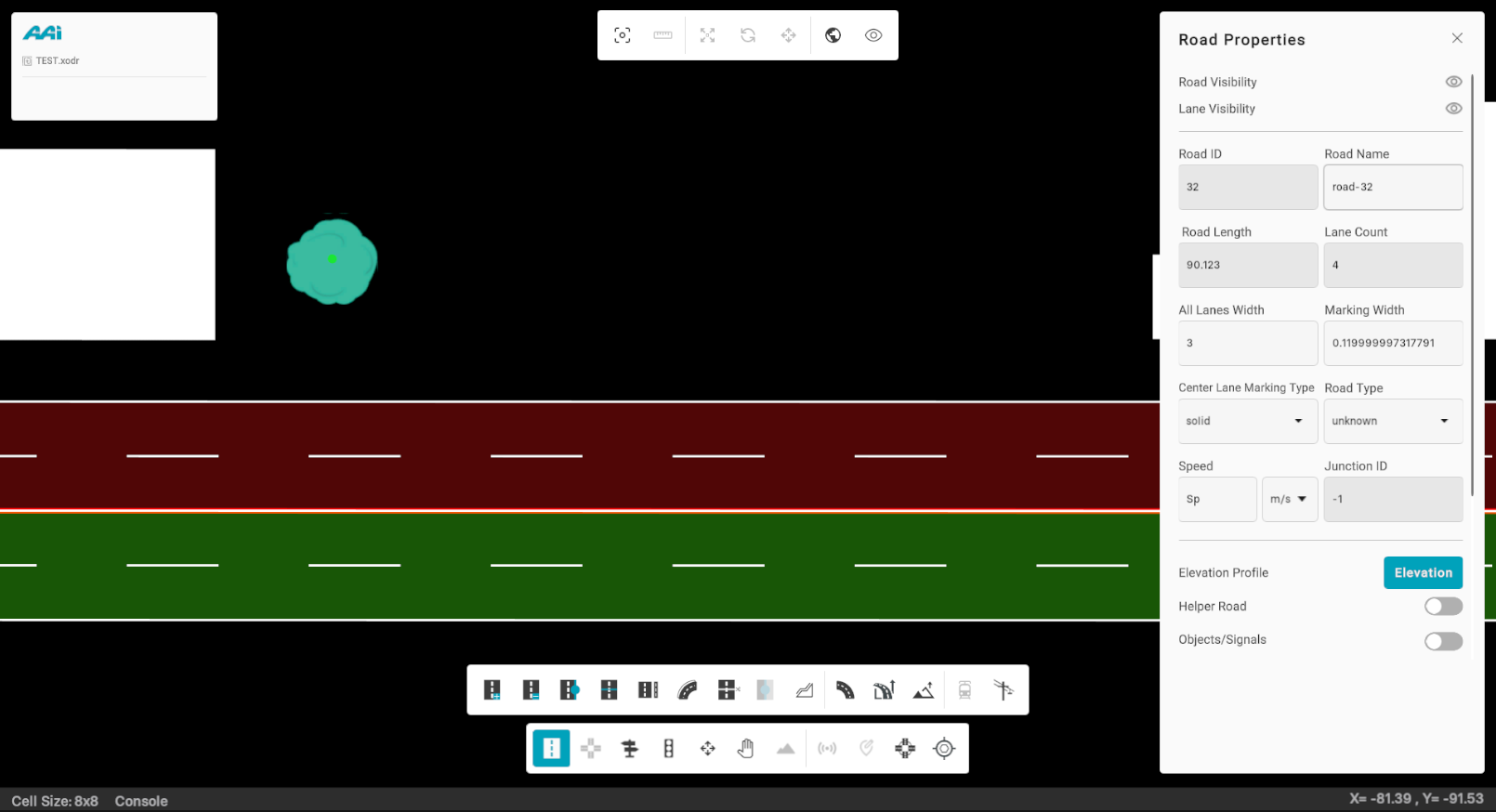
2. Click the eye icon on the right side of "Road Visibility" using the primary (usually left) mouse button.
Show Road
This tool enables the user to make a previously hidden road visible again on the map. When activated, the user can select from a list of hidden roads or click on the desired road’s location if known. Once selected, the road will reappear in the grid window with its original geometry and attributes. This helps restore the full layout of the map when needed.
Approach #1: Directly through "Road Properties" panel
1. Click the desired road with the primary (usually left) mouse button to open its properties panel.
2. Click the eye icon on the right side of "Road Visibility" using the primary (usually left) mouse button. This will remove the hidden effect on the eye and enable the road for view once again.
Approach #2: Using the shortcut
Hold the "Shift + S" hotkey combination to make the most recently hidden road visible again.
Lanes
While creating a map in RepliMap, first add a road in your map (by default, two lanes are added to right-side of the road), now follow the steps below to include more lanes in either side of that road.
Adding Lanes
1. Select a road by using the "Edit Road" tool by clicking with the primary-mouse button (usually left) on it.
2. Select the "Lane Tool" sub-tool from the editor bar.

3. Move the mouse to either horizontal extremity of the road and using the primary-mouse button (usually left) click to either side to add a lane. Depending on what side of the road is clicked, lanes will be added accordingly.

Deleting Lanes
Select the "Lane Tool" from the toolbox, and press the secondary-mouse button (usually right) on the desired lane to remove it.
Lane Visibility
Hide Lane
This tool allows the user to temporarily hide the lanes of a road from the map without deleting them. Once selected, the lanes will be removed from view in the grid window, but their geometry and attributes remain intact. This is useful for decluttering the map or focusing on other components during editing.
1. Click the desired road with the primary (usually left) mouse button to open its properties panel.
2. Click the eye icon on the right side of "Lane Visibility" using the primary (usually left) mouse button.
Show Lane
This tool enables the user to make a previously hidden lanes in a road visible again on the map. Once selected, the lanes will reappear in the grid window with its original geometry and attributes. This helps restore the full layout of the map when needed.
Approach #1: Directly through "Road Properties" panel
1. Click the desired road with the primary (usually left) mouse button to open its properties panel.
2. Click the eye icon on the right side of "Lane Visibility" using the primary (usually left) mouse button. This will remove the hidden effect on the eye and enable the road for view once again.
Approach #2: Using the shortcut
Hold the "Shift + S" hotkey combination to make the most recently hidden lanes visible again.
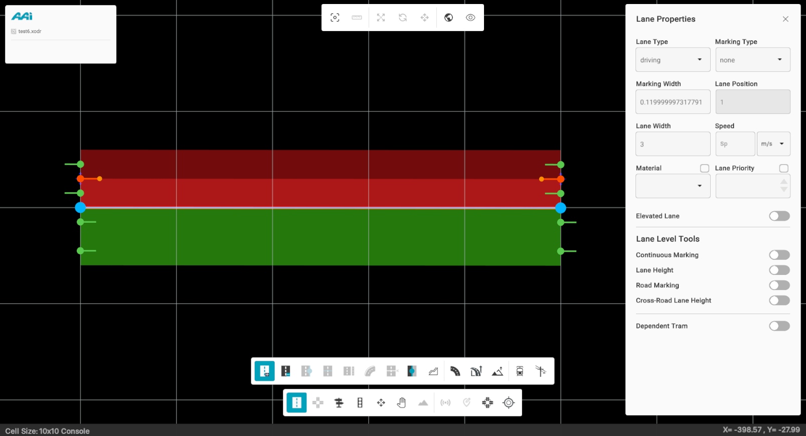
Lane Level Tools
These properties are accessible through the lane-level properties panel within a selected road. This panel allows users to customize various lane features, supporting better design practices while aligning with the aesthetic requirements of the road.
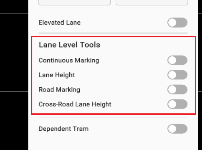
Continuous Marking
It allows the user to place anchors for lane-level styling. This feature enables the placement of continuous road markings across a section without needing to add multiple individual anchors—streamlining the process and promoting best practices for managing multiple sections.
Approach #1: Through the "Continuous Marking" toggle
1. Triple-click the desired lane on the selected road using the primary (usually left) mouse button to open its properties panel.
2. Toggle the "Continuous Marking" switch. When enabled, it will turn cyan. A confirmation notification will appear if activated successfully.
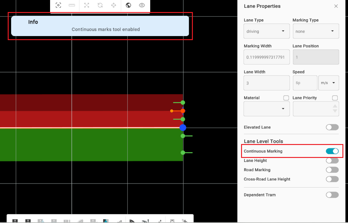
3. Once enabled and with a lane selected, hover over the desired area on the lane and press the "A" hotkey to add a continuous road marking anchor. Clicking the marking will display its properties. To delete it, simply hover over it and press the "D" hotkey.
Approach #2: Through the hotkey
1. Triple-click the desired lane on the selected road using the primary (usually left) mouse button to open its properties panel.
2. Toggle the "Continuous Marking" by pressing the "W" hotkey. When enabled, it will turn cyan. A confirmation notification will appear if activated successfully.
3. Once enabled and with a lane selected, hover over the desired area on the lane and press the "A" hotkey to add a continuous road marking. Clicking the marking will display its properties. To delete it, simply hover over it and press the "D" hotkey.

Lane Height
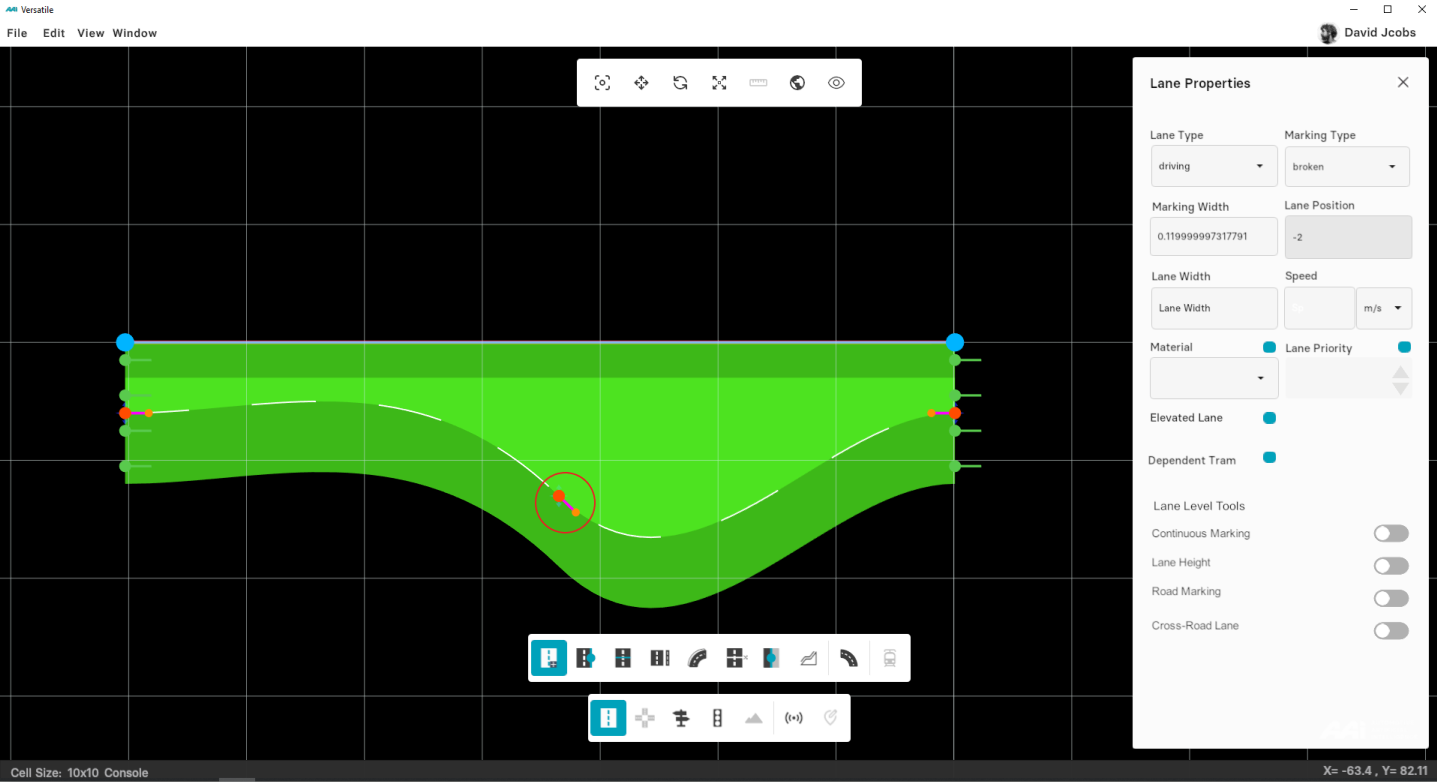
Allows the user to place an anchor that controls the elevation of a lane at a specific point. This anchor is draggable, enabling smooth adjustments to the lane’s vertical profile along its path.
Inner/Outer Height Adjustment
When modifying lane elevation, users can also adjust inner and outer height offsets along the lane borders.
In OpenDRIVE (ODR), these offsets are defined per lane border.
Currently, markers may appear on the topmost lane instead of the active one — to fix this:
- Select the correct lane by triple-clicking on it to activate its properties.
- Ensure that the inner and outer circle markers map to the selected lane’s borders.
- A visual highlight of the active lane will appear before applying height adjustments.
Note: Editing and moving anchors in tilted (3D) view is not supported — lane editing remains available in 2D view only.
2. Toggle the "Lane Height" switch. When enabled, it will turn cyan.
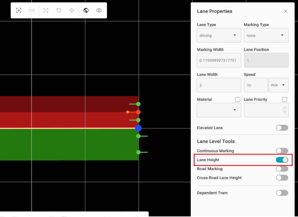
3. Once enabled and with a lane selected, hover over the desired area on the lane and press the "A" hotkey to add a road marking anchor. Clicking the marking will display its properties. To delete it, simply hover over it and press the "D" hotkey.
Approach #2: Through the hotkey
1. Triple-click the desired lane on the selected road using the primary (usually left) mouse button to open its properties panel.
2. Toggle the "Lane Height" by pressing the "E" hotkey. When enabled, it will turn cyan.
3. Once enabled and with a lane selected, hover over the desired area on the lane and press the "A" hotkey to add a continuous road marking. Clicking the marking will display its properties. To delete it, simply hover over it and press the "D" hotkey.
Road Marking
It allows the user to place anchors for lane-level styling. This feature enables the placement of road markings across a section.
Approach #1: Through the "Road Marking" toggle
1. Triple-click the desired lane on the selected road using the primary (usually left) mouse button to open its properties panel.
2. Toggle the "Road Marking" switch. When enabled, it will turn cyan.
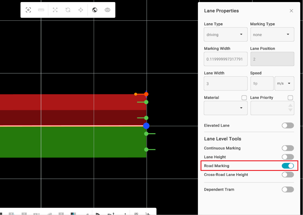
3. Once enabled and with a lane selected, hover over the desired area on the lane and press the "A" hotkey to add a road marking anchor. Clicking the marking will display its properties. To delete it, simply hover over it and press the "D" hotkey.
Approach #2: Through the hotkey
1. Triple-click the desired lane on the selected road using the primary (usually left) mouse button to open its properties panel.
2. Toggle the "Continuous Marking" by pressing the "R" hotkey. When enabled, it will turn cyan.
3. Once enabled and with a lane selected, hover over the desired area on the lane and press the "A" hotkey to add a continuous road marking. Clicking the marking will display its properties. To delete it, simply hover over it and press the "D" hotkey.

Cross-Road Lane Height
Information is currently unavailable in the latest RepliMap version.
Lane Marking
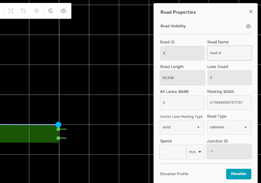
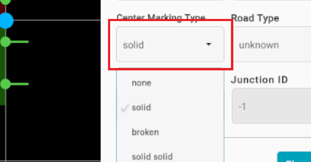
Allows the user to change the designated lane markings based on their preferences. By default, a solid line appears along the center of the road, but this can be modified, along with individual lane markings, at the lane level.
Changing the reference line marking
1. Click the desired road with the primary (usually left) mouse button to open its properties panel.
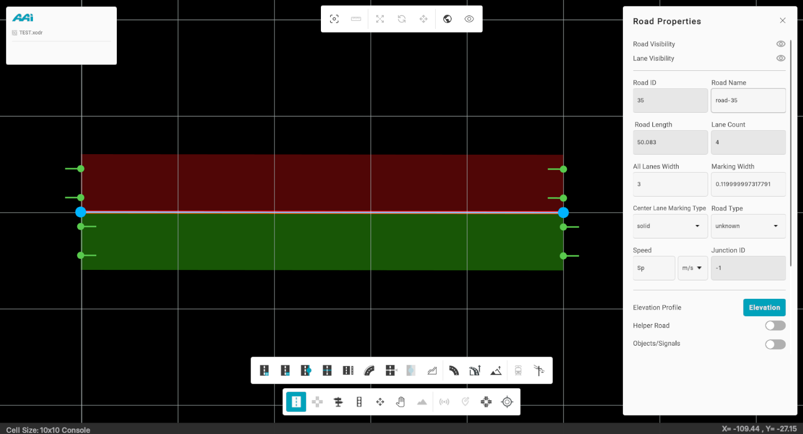
2. Open the "Center Line Marking Type" dropdown and select the desired marking type.
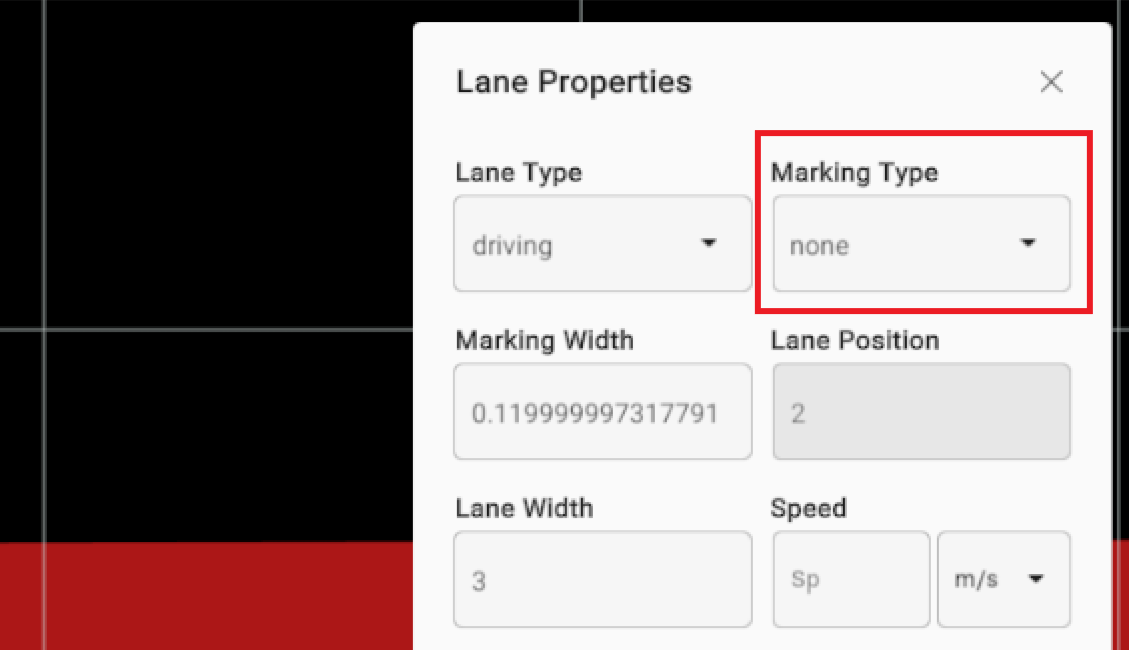
Changing specific lane marking
1. Triple-click the desired lane on the selected road using the primary (usually left) mouse button to open its properties panel
2. Open the "Marking Type" dropdown and select the desired marking type.
Lane Section
This sub-tool inside of the Road Edit tool allows the user to divide the existing road into two or more sections. It also enables adding and deleting lane sections within the same interface.
Adding a Lane Section
1. Select the "Road Edit" tool and click on "Lane Section" sub-tool.
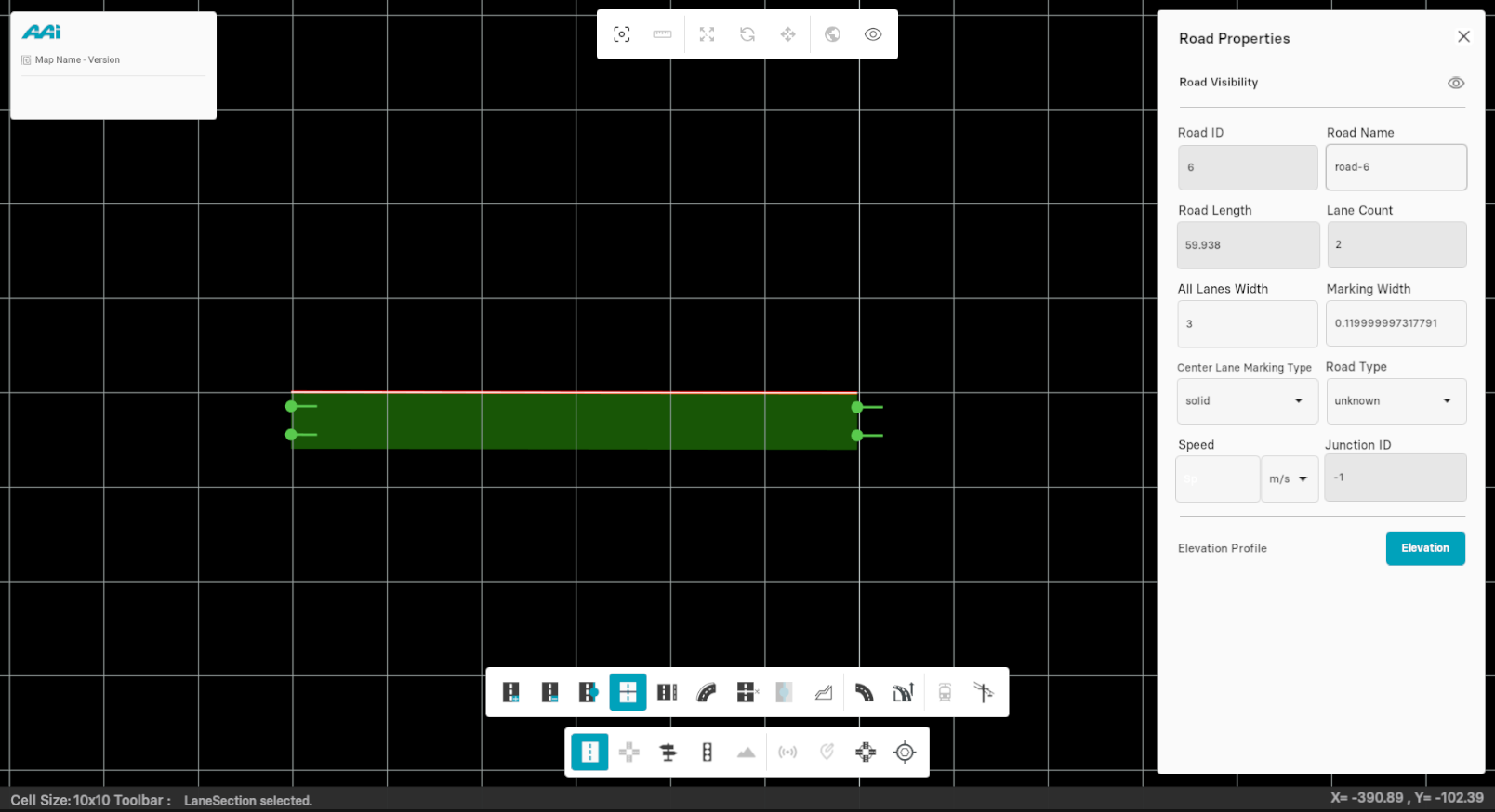
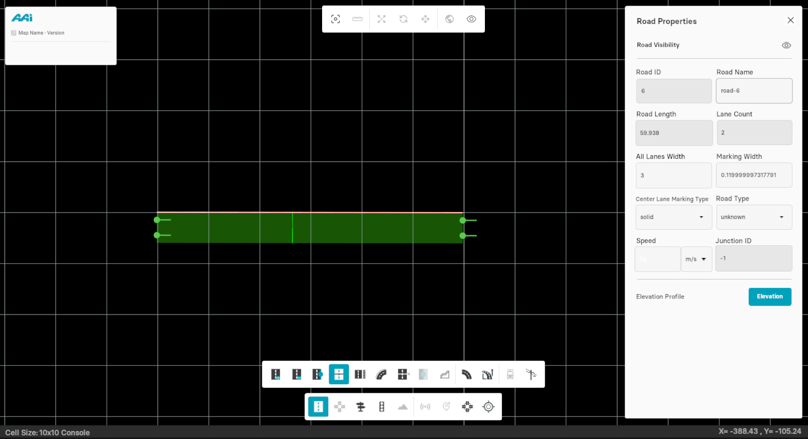
2. Now, move your cursor towards the selected road and click at desired position on the road to add a lane section.
Delete Lane Section
Choose Delete lane Section to delete any existing section from any lane of the road.
1. Use your secondary-mouse button (usually right) on a lane section within the road.
Note that if no lane section is clicked and only the road is clicked, lane sections will be removed in a First-In, First-Out (FIFO) order.
Move Lane Section
This tool helps to adjust the position of formerly added section to the lane.
1. Select the "Road Edit" tool and click on "Lane Section" sub-tool.
2. Hold primary-mouse button (usually left) + "left ctrl" on top of the section line and drag to reposition it.
Lane Offset
This sub-tool (inside of the "Road Edit" tool) allows the user to shift the lane profile instead of shifting the reference line. The lane offset defines a lateral shift of the lane reference line (which is usually identical to the road reference line).
Add Lane Offset
1. Select the road by selecting the "Road Edit" tool from the editor bar.
2. Go to the "Road Edit" tool and choose the "Lane Offset" sub-tool.

3. Hold and drag the existing anchor inside of the road with the primary-mouse button (usually left). Note that you're only able to move the anchors in a vertical movement.
Add Lane Offset Anchors
Hold "left ctrl" and click with the primary-mouse button (usually left) on desired the position to add a new anchor.
Move Lane Offset Anchors
Hold primary-mouse button (usually left) on top of the lane offset anchors and drag it to change the geometry of the road.

Delete Lane Offset Anchors
Hold "left shift" and click primary-mouse button (usually left) on the anchor to delete it. By doing this, the current geometry of the road reverts back to the original geometry from the end-to-end anchor points.
Note that if for a lane section no lane offset record is defined, the lane reference line is identical to the road reference line.
Dependent Tram
Enables users to create an accurate dependent tram system based on tram specifications, facilitating a more precise and efficient map development experience.
1. Select the "Edit Road" tool. Select the lane by triple-clicking it with the primary-mouse button (usually left) on a lane.
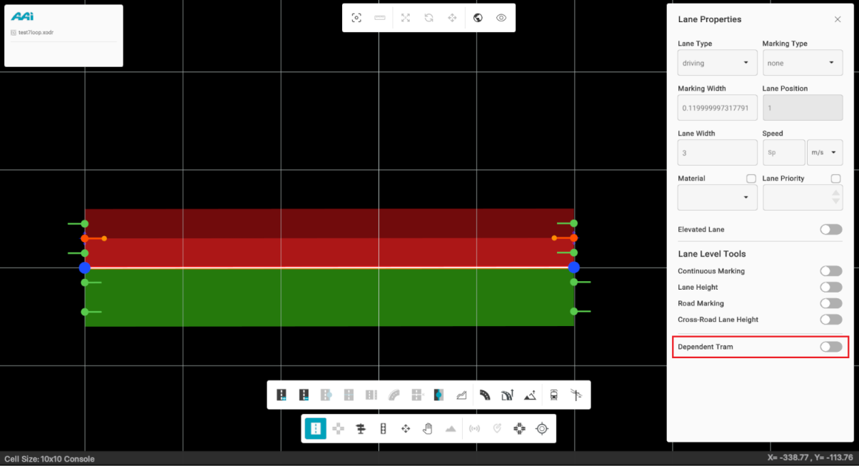
2. Toggle the "Dependent Tram" switch. When enabled, it will turn cyan.
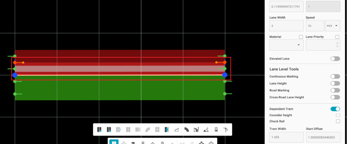
3. A properties panel will appear below the Dependent Tram toggle. This panel allows you to customize various tram settings based on the required specifications.
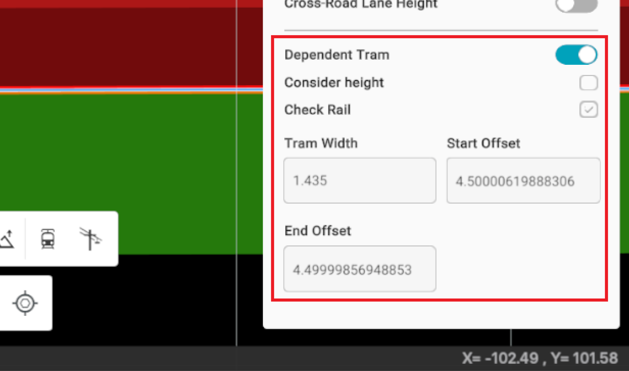
Hiding the road while the dependent tram is enabled will only hide the parent road, not the dependent tram track itself. This can be useful for creating precise tram connections without interference from the main road layout.

Width Tag
This sub-tool allows the user to edit the width and some existing properties of a particular lane within a road.
Adding Width Tags
1. Select the "Edit Road" tool. Select the lane by triple-clicking it with the primary-mouse button (usually left) on a lane.

2. Equip the "Width Tag" sub-tool" and primary-button click (usually left) at any desired point on the selected lane to add a width tag on it.

Moving Width Tags
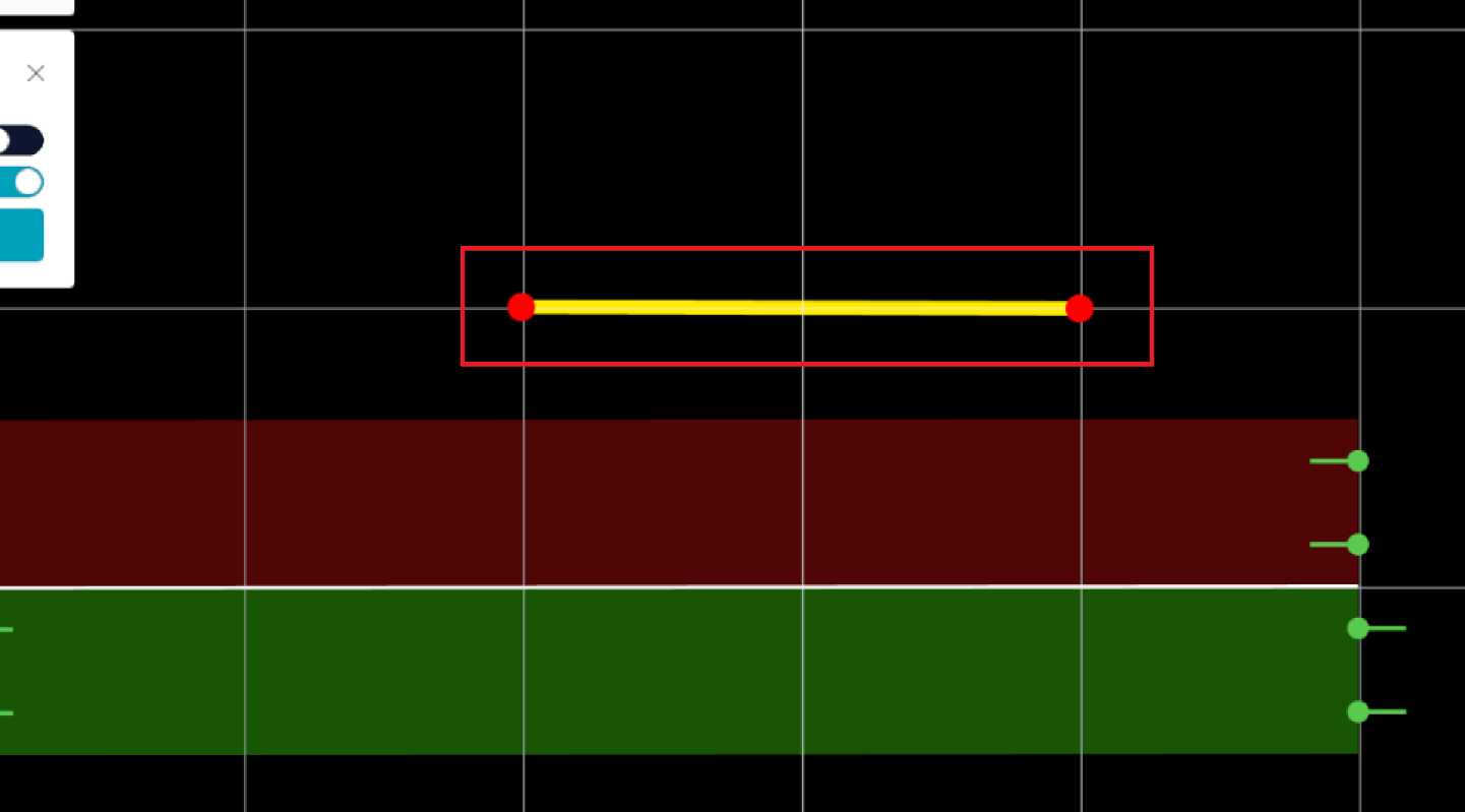
When a width tag has been added, the user is able to change the width of that lane manually.
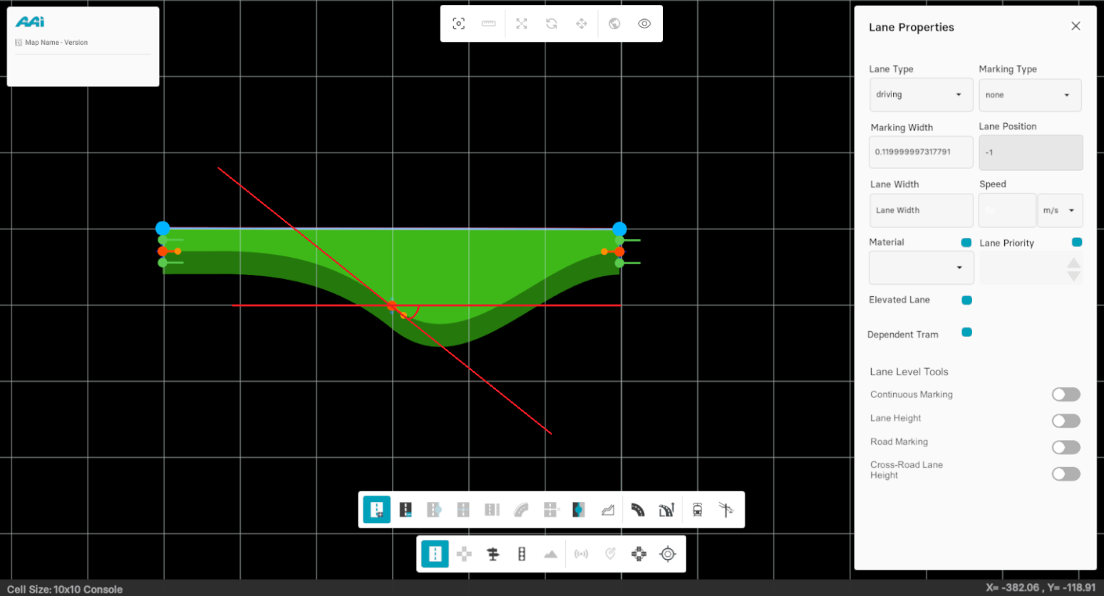
1. Unequip the sub-tool (maintain the "Road Edit" tool equiped), drag the head of the tag in dark orange to change the width along the road's normal. This can only be done vertically.
2. Drag the tail of the width tag to change the heading of the width as shown in figure below.
Delete Width Tag
1. Select "Road Edit" from the editor bar, and triple-click using the primary-mouse button (usually left) on desired lane (where the width tag is located).
2. Hover on top of the width tag and right-click on the existing width tag.
Road Anchor
This sub-tool allows the user to add a new anchor point on the lane that lets you modify the geometry of the road.
Inserting Anchors
1. Select a road by using the "Edit Road" tool by clicking with the primary-mouse button (usually left) on it.
2. Select the "Road Anchor" sub-tool from the toolbox.
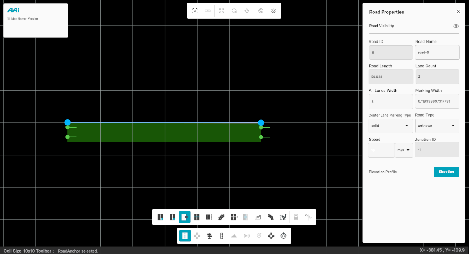
3. Click using the primary-mouse button (usually the left) on the existing road to insert another anchor point.
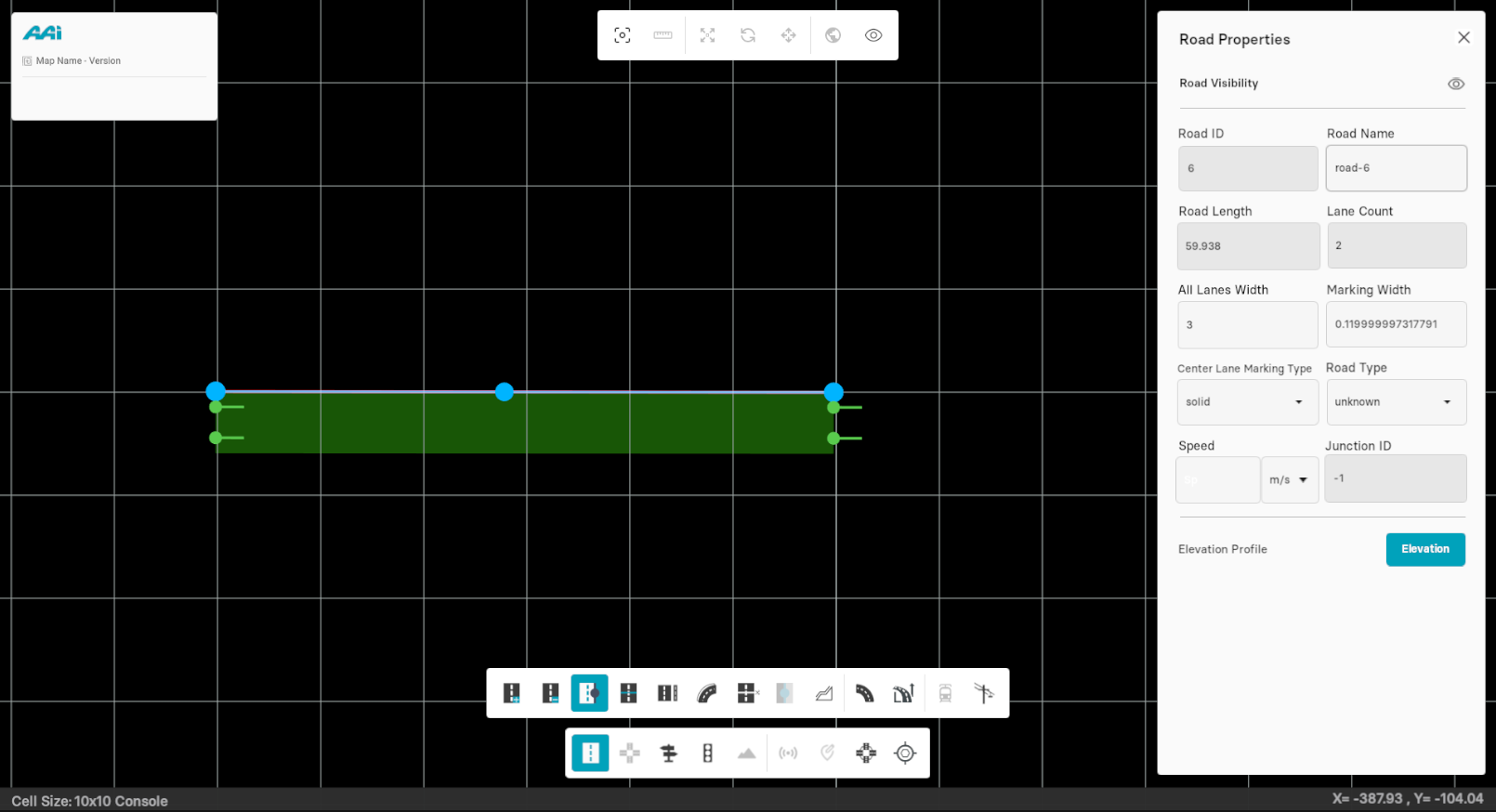
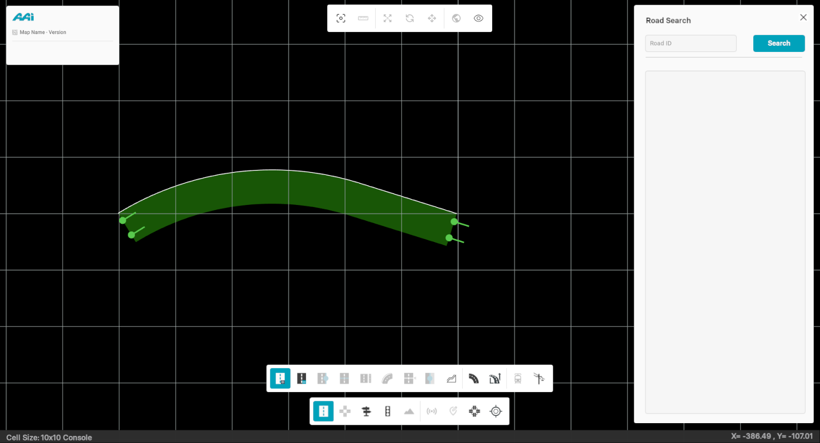
4. Unequip the sub-tool from the editor bar (keep the "Road Edit" tool equiped). It should now allow you to drag the anchor point to change the geometry of the road.
Deleting Anchors
This tool terminates the anchor points from the road. Thus, the road returns to its original profile.
Select the desired road. Go to editor bar, select "Road Anchor" from the tools and right click on the anchor point to delete it.
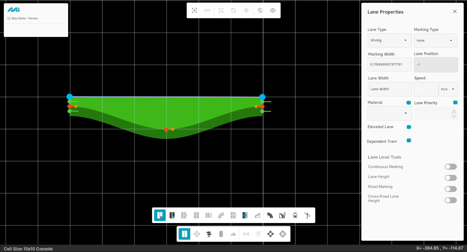
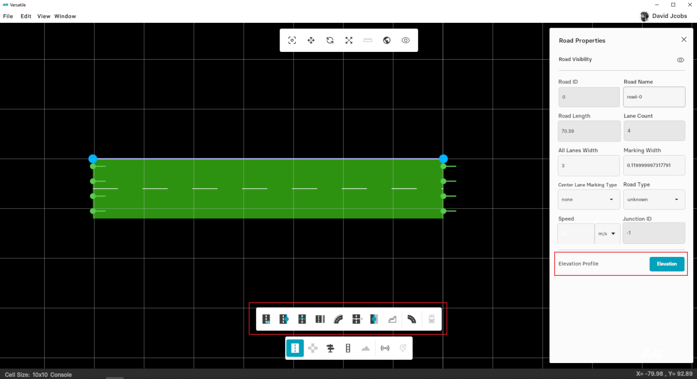
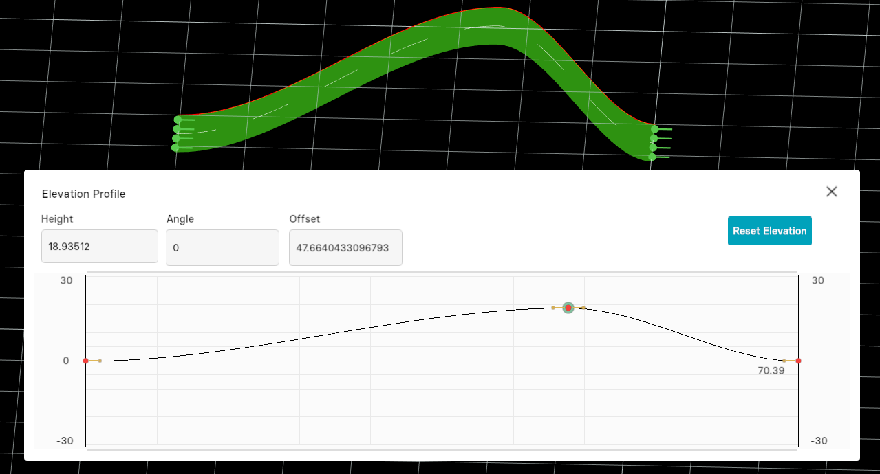
Elevation Profile
This option allows the user to define Height , Angle, and Offset to the existing road in the map.
Set Elevation
1. Select the existing road in the map. Click on "Elevation Profile" from parameters pane at the left-side of the RepliMap window. Note that no "sub-tools" should be selected.
2. Click using secondary-mouse button (usually right) at any point to add anchor points inside the grid within the "Elevation Profile" window.
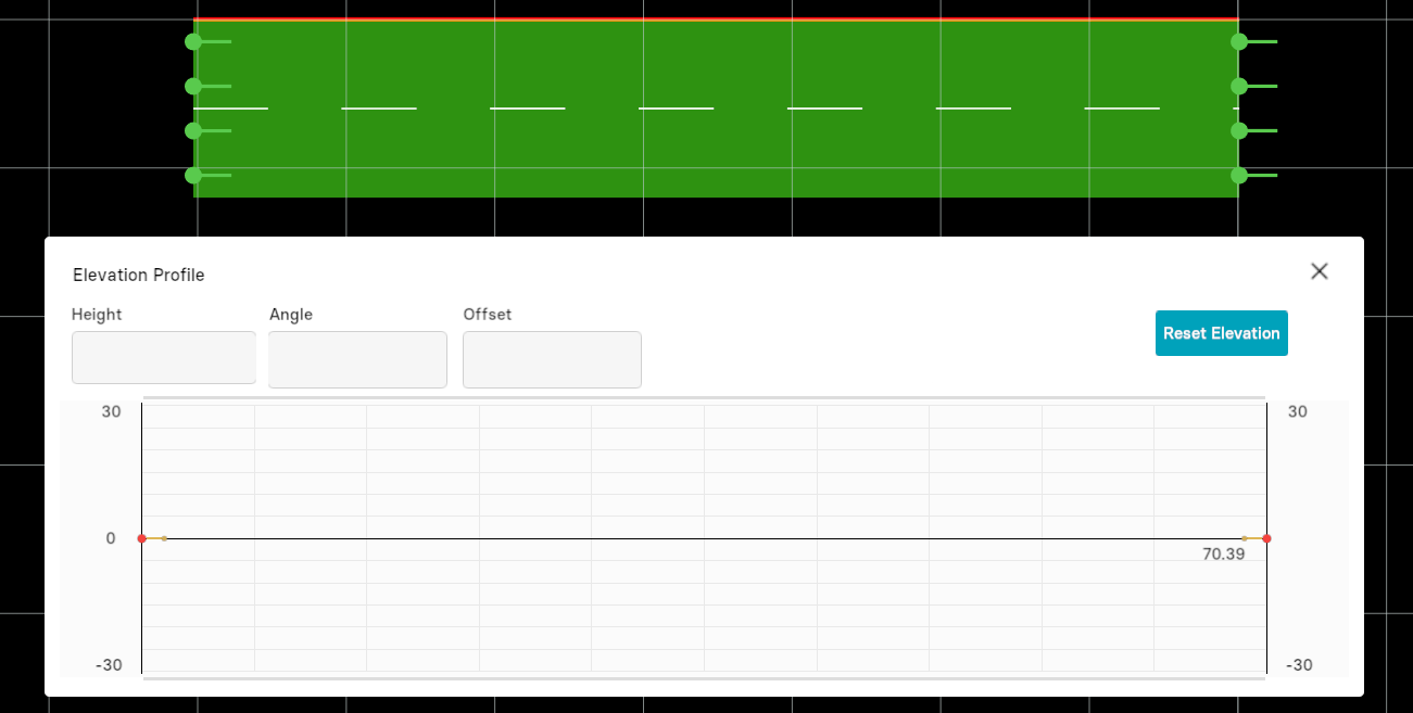
3. Close the "Elevation Profile" window. Hold "left alt" and click using the primary-mouse-button (usually left) to view the elevation profile of the selected road.
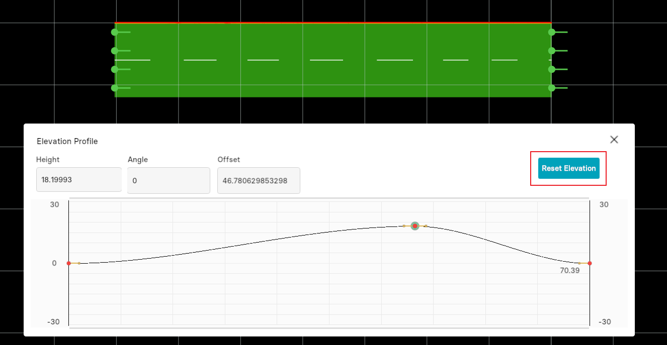
Reset Elevation
From the "Elevation Profile" window, select the "Reset Elevation" option to revert to its initial position.
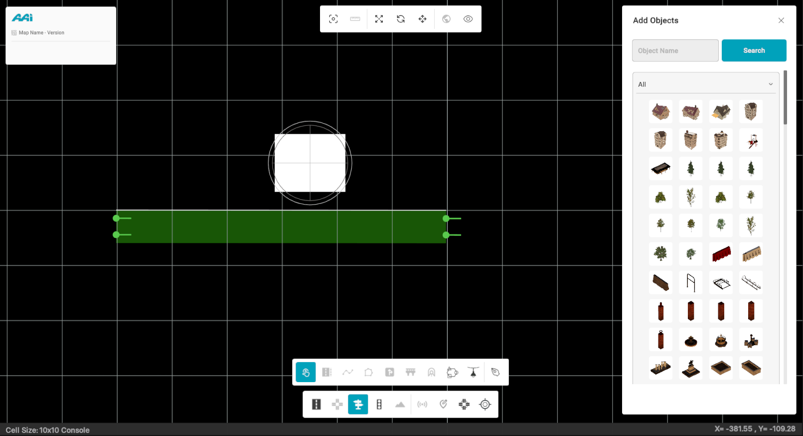
Objects
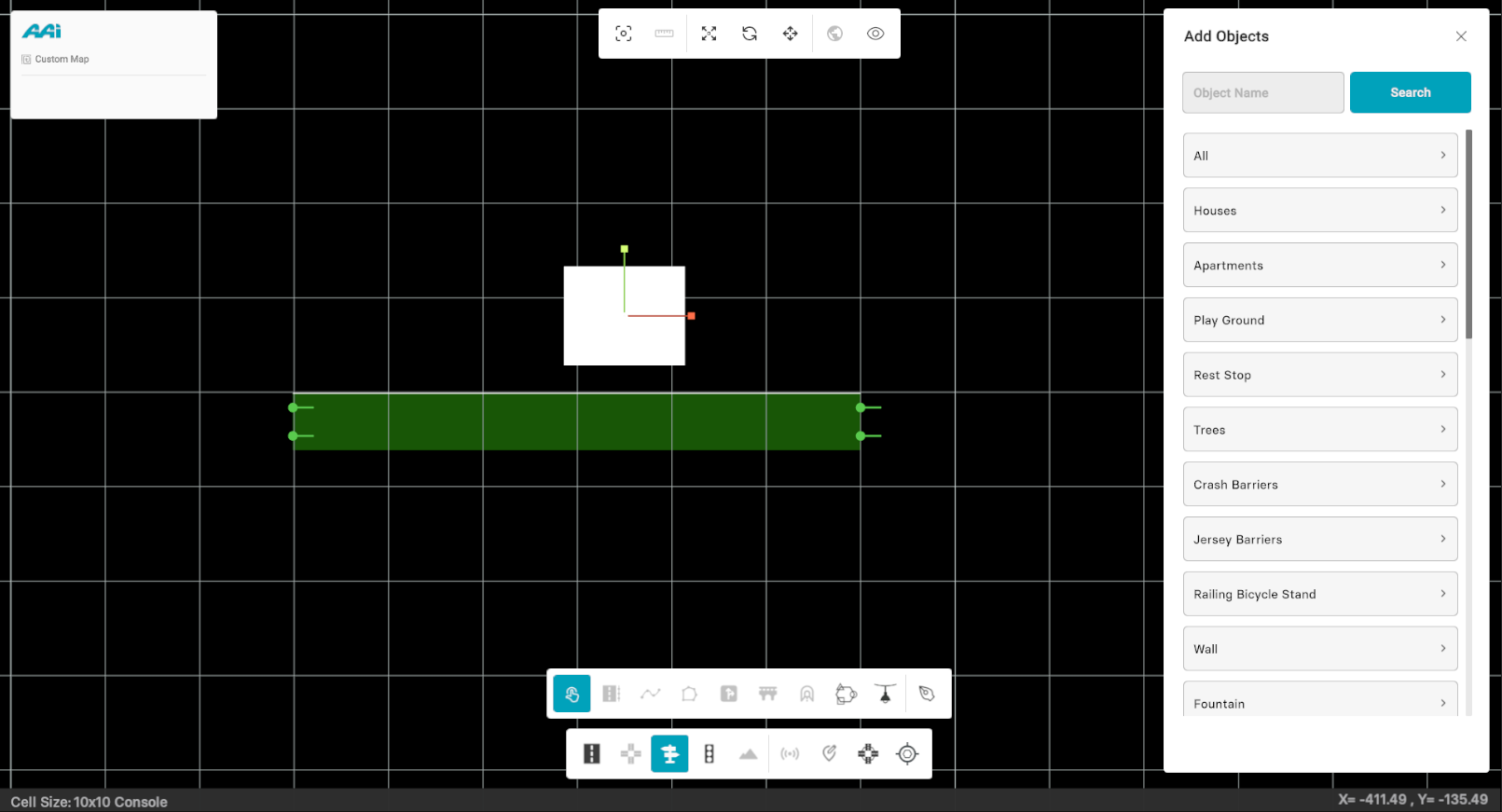
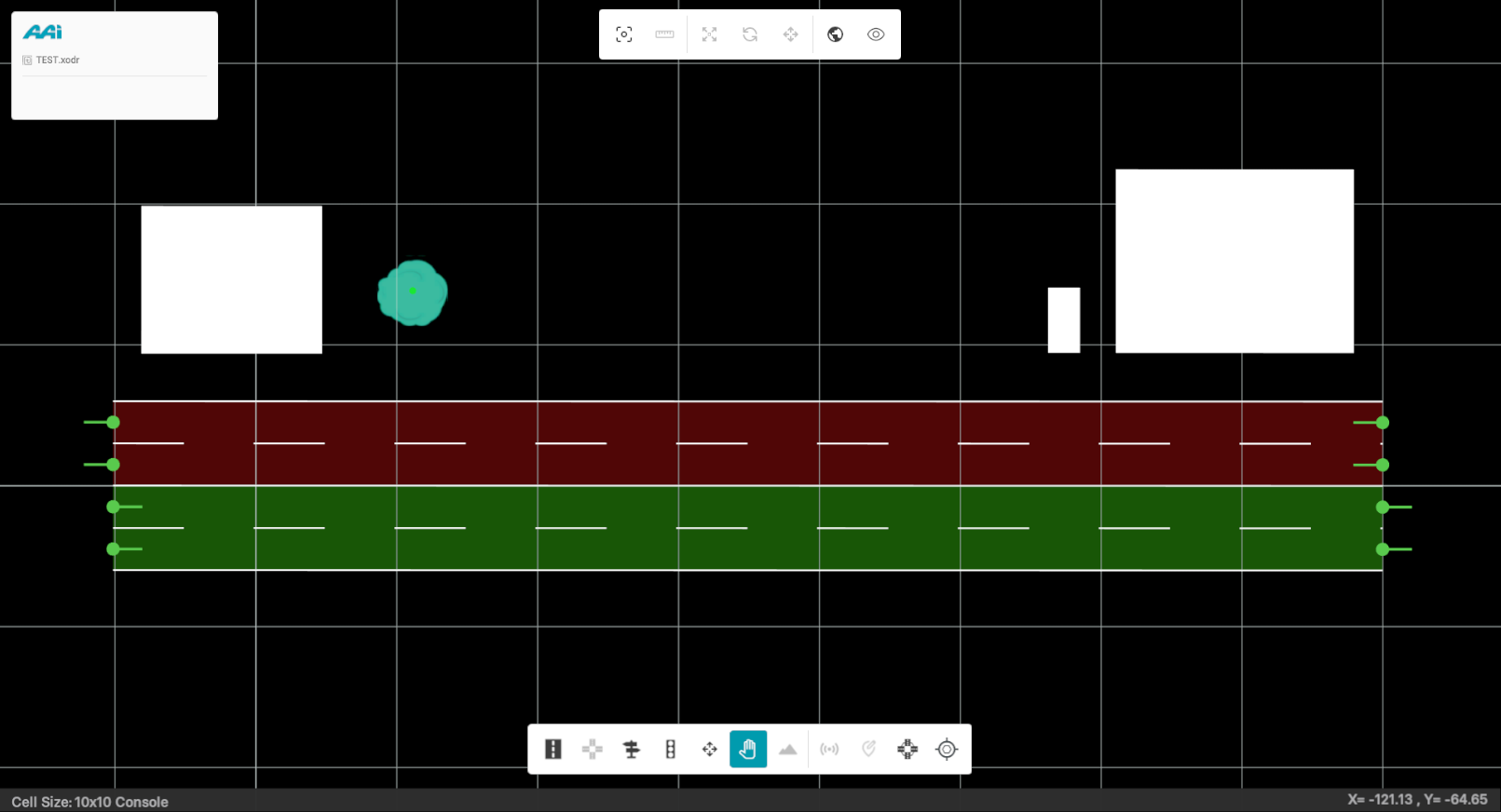
Allows the user to place objects inside of the selected road. When selected, the object menu display will be provided on the right side of the mapping platform. Use secondary click to highlight the road for object placement (most commonly right click)
Adding Objects
1. From the Editor Bar, select the "Add Objects" tool.
2. Click the "Single Object" tool displayed once the "Add Objects" tool is selected.
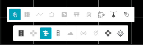
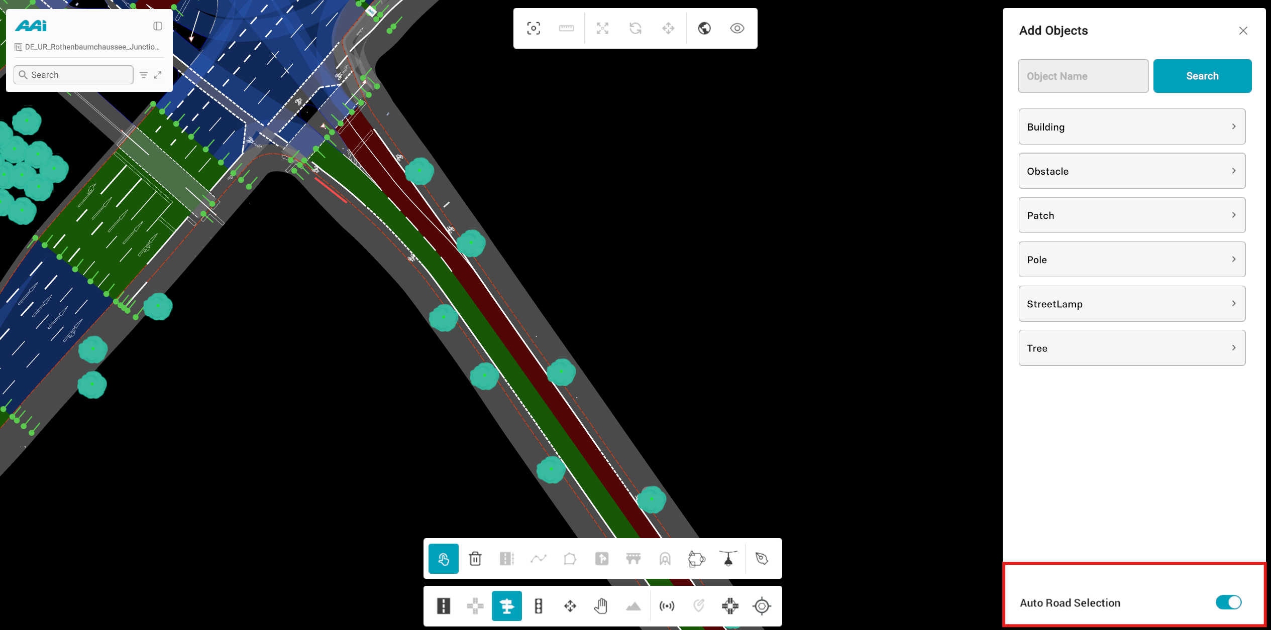
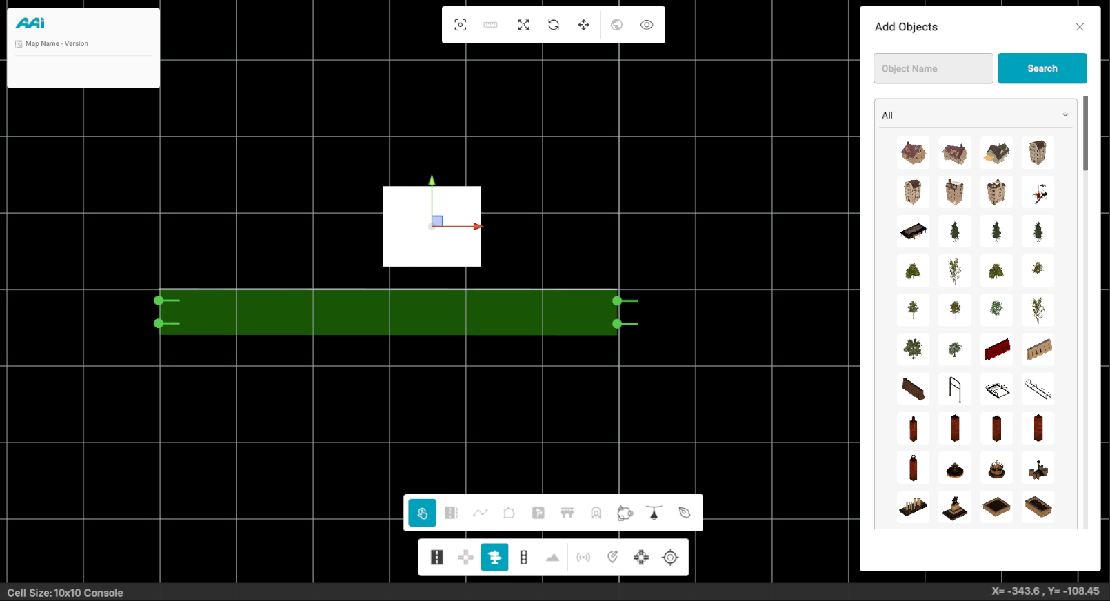
3. The "Add Objects" panel displays all available signal options and alternatives categorized by type. Users can then select and drag items onto the map as needed.
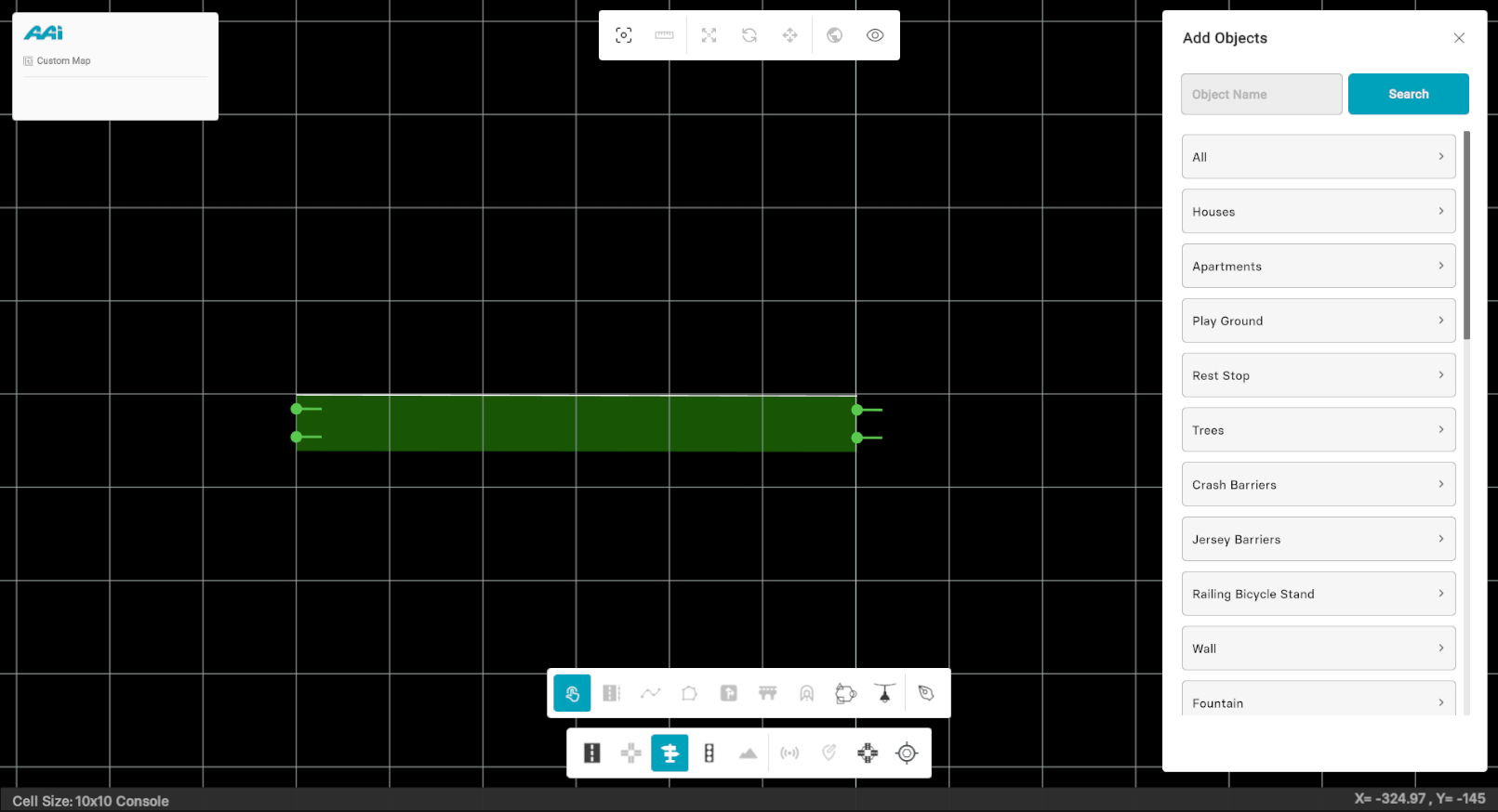
4. Drag and drop an object to any desired position on the road while the "Objects" tool is selected.
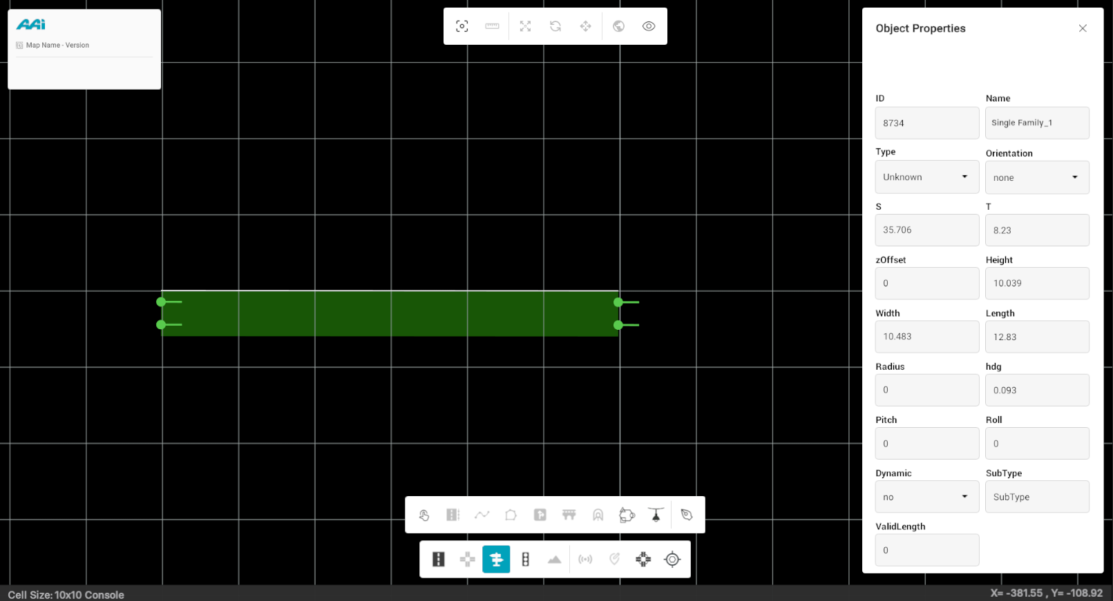
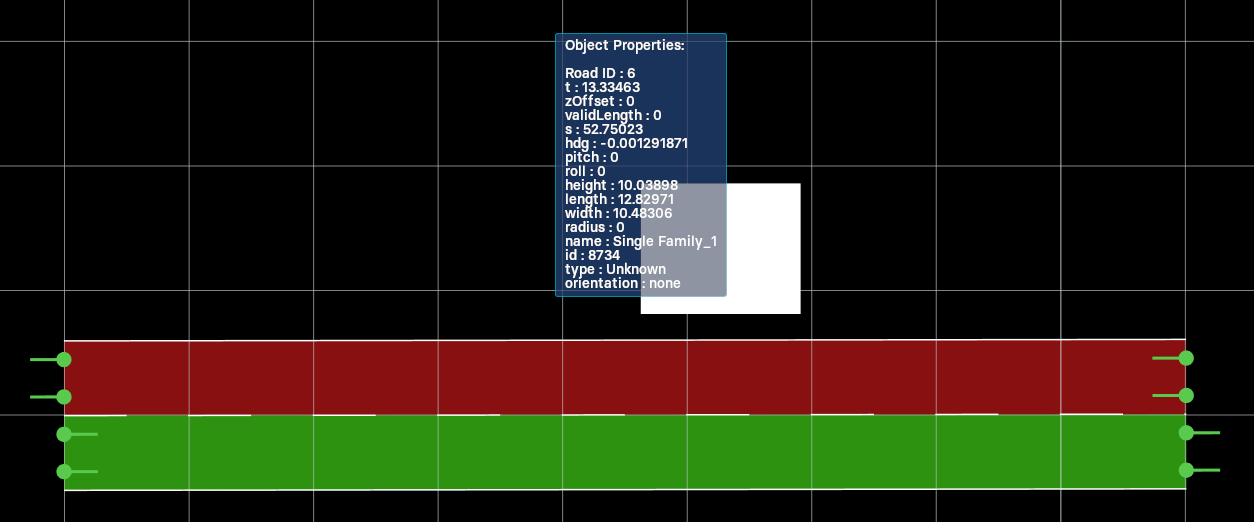
5. To select the object properties, deselect the "Objects" tool and click on the object to visualize its properties on the right panel.
You can adjust the desired properties as needed to suit the situation and meet the user's specific requirements using the right panel.
Auto Road Selection
The Auto Road Selection toggle helps streamline object placement from the library.
- When enabled, RepliMap will automatically detect and attach the selected object (e.g., building, pole, or tree) to the nearest road when you drag and drop it into the scene.
- When disabled, you must manually select a road by right-clicking on it before placing any object.
This feature ensures that placed objects maintain proper alignment with road geometry, improving accuracy and reducing manual adjustment.
Moving Objects
1. Select the "Objects" tool from the editor bar.
2. Click on the object using the primary-click button (usually left). By default, the "Move" (also selectable through a shortcut "W") option will be enabled.
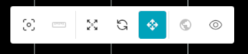

This will display the X and Y axis arrows relative to the object.
Rotating Objects
1. Select the "Objects" tool from the editor bar.
2. Once hovering over the object, primary-mouse button (usually left) click on it. Make sure you have the "Rotate" option (also selectable through a shortcut "E") selected.
Selecting the option will display a 360-degree radial selection wheel to indicate the specific rotation of the selected object.
Scaling Objects
1. Select the "Objects" tool from the editor bar.
2. Once hovering over the object, primary-mouse button (usually left) click on it. Make sure you have the "Scale" option (also selectable through a shortcut "R") selected.
This will display the X and Y axis arrows relative to the object.
Signals
Allows the user to place signals as part of the selected or near-by road. When selected, the signal menu will be provided on the right side of the mapping platform.
Adding Signals
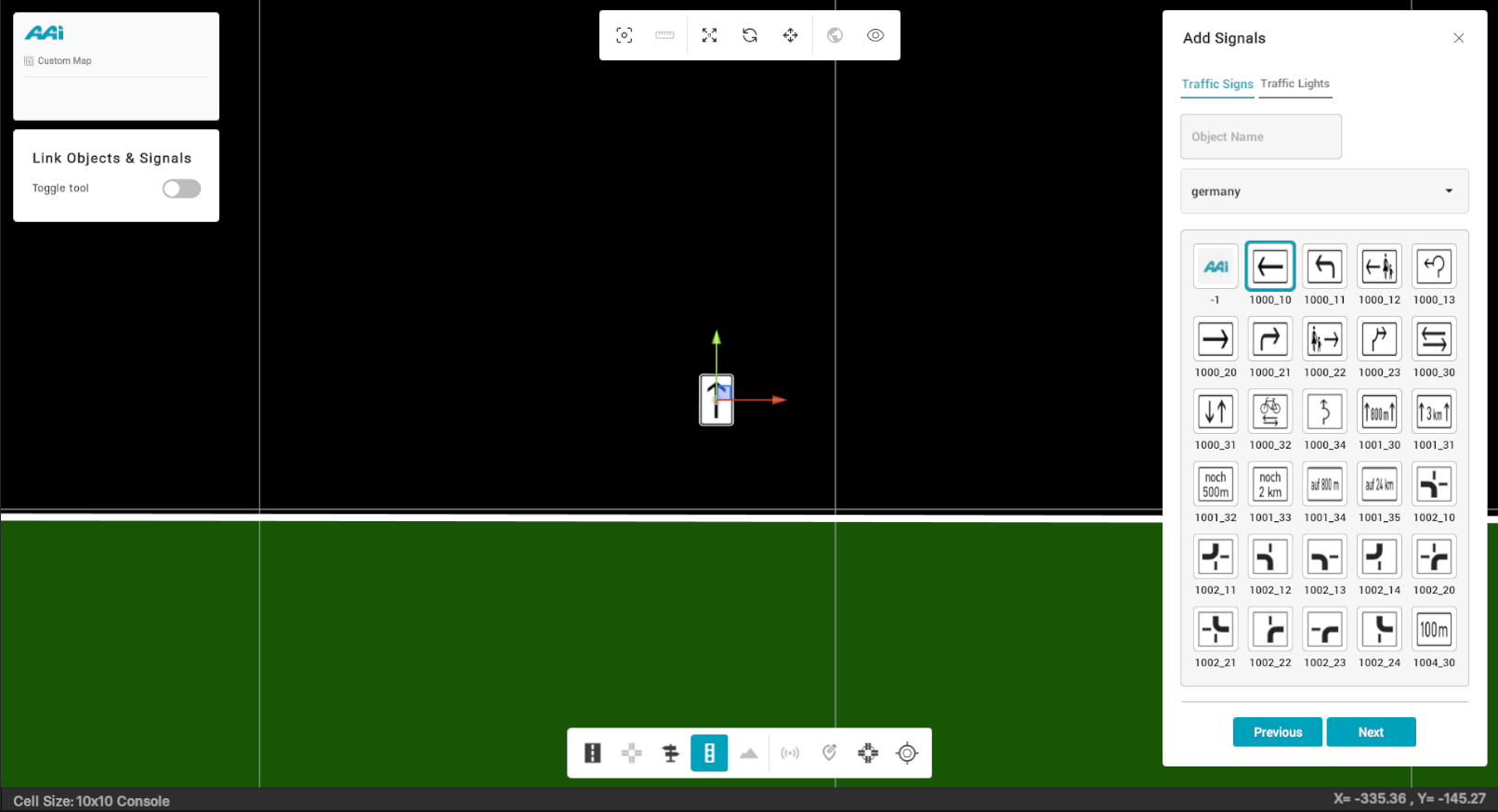
1. Select the "Signals" tool from the editor bar.
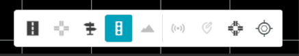
2. The "Signals" side panel will displays all available object options and alternatives categorized by location and traffic type (signs / lights).
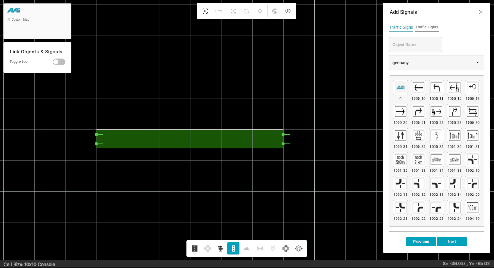
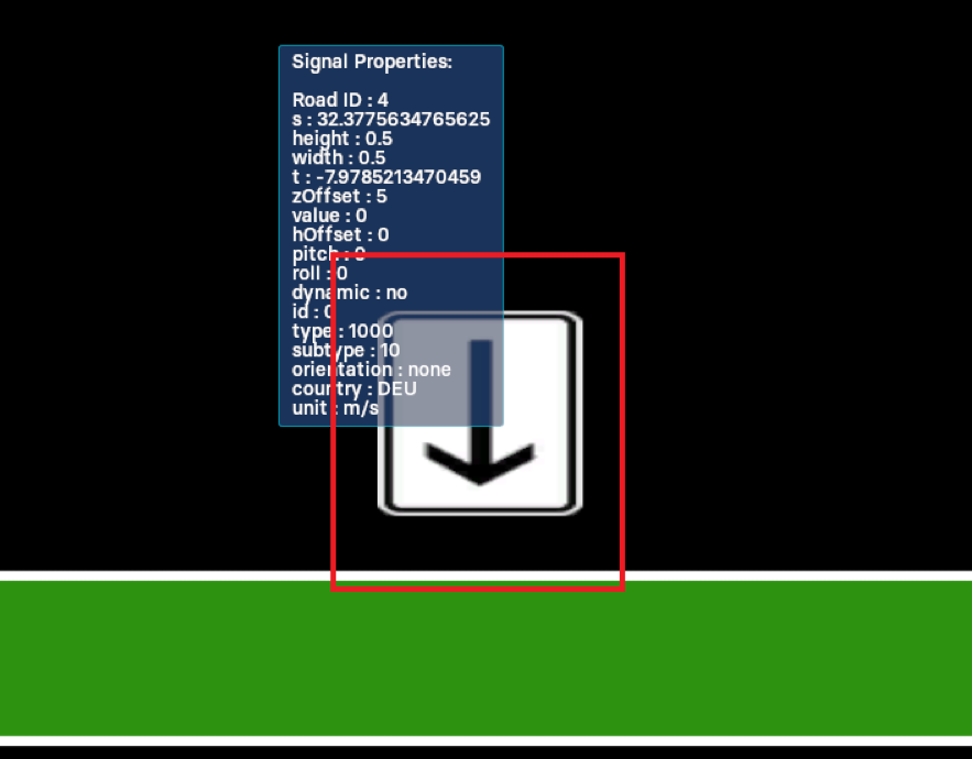
3. Drag and drop a signal to any desired position on the road while the "Signals" tool is selected. When you hover over the signal with the "Signals" tool deselected, the signal's properties will be displayed.
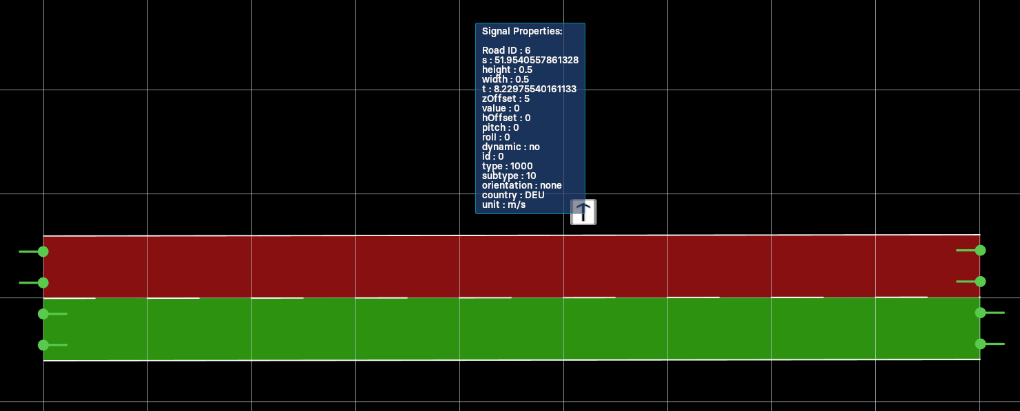
4. To select the signal properties, deselect the "Signals" tool and click on the object to visualize its properties on the right panel.
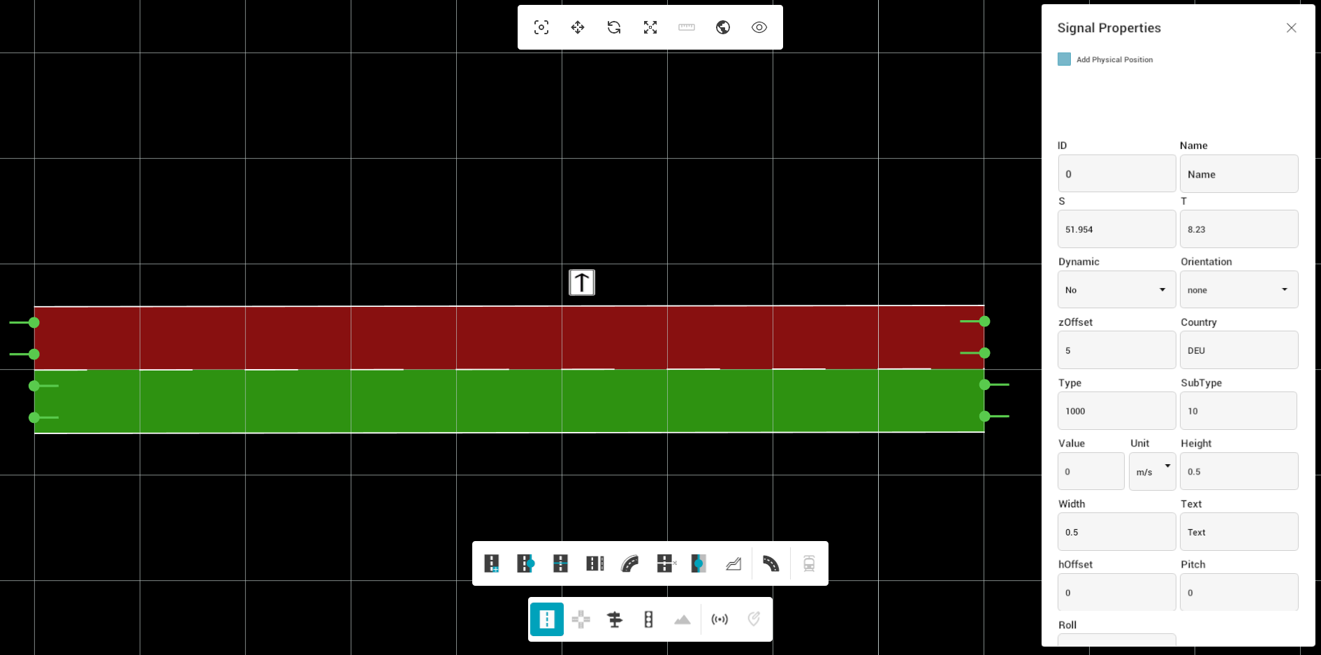
5. You can adjust the desired properties as needed to suit the situation and meet the user's specific requirements. More content information (such as Lane Validity) can be seen if scrolled down through the panel.
Moving Signals
1. Hover over the signal while the "Signals" selection is active in the editor bar.
2. Once hovering over the signal, click on it. By default, the "Move" (also selectable through a shortcut "W") selection will be enabled.
3. This will display the X and Y axis arrows relative to the signal.
Rotating Signals
1. Hover over the signal while the "Signals" selection is active in the editor bar.
2. Once hovering over the signal, click on it. Make sure you have the "Rotate" option (also selectable through a shortcut "E") selected.
3. This will display a 360-degree radial selection wheel to indicate the specific rotation of the selected signal.

Scaling Signals
1. Hover over the signal while the "Signals" selection is active in the editor bar.
2. Once hovering over the signal, click on it. Make sure you have the "Scale" option (also selectable through a shortcut "S") selected.
3. This will display the X and Y axis arrows relative to the signal.

Objects & Signals
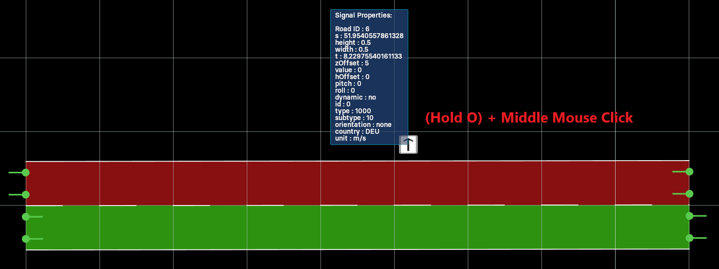
Deleting Objects and Signals
To delete an object or signal, the user must hover over the corresponding object/signal and use a designated hotkey combination.
Hold "o" and click over the signal/object using the "middle-mouse button".
Move ObjSig
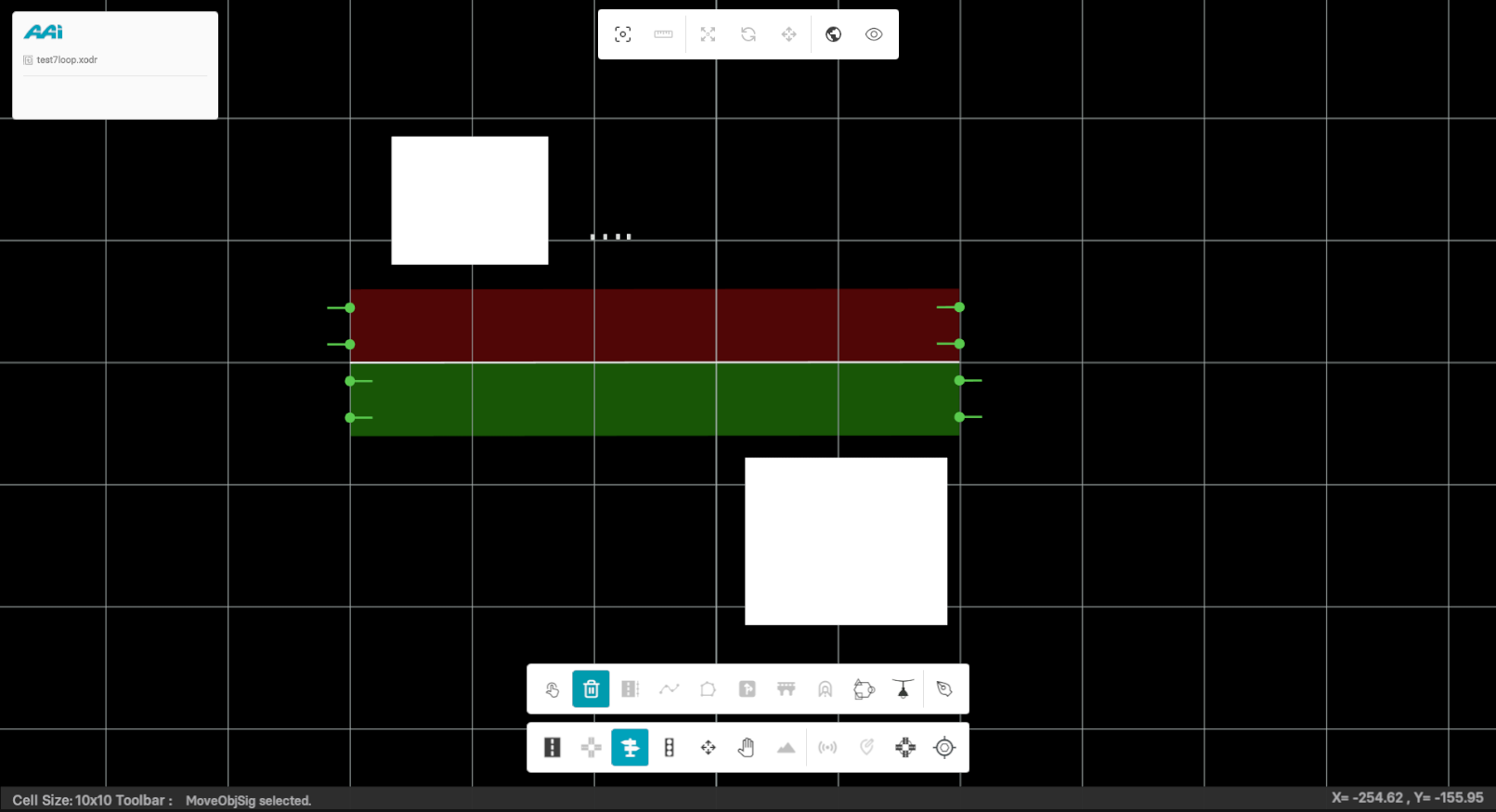
To move multiple objects and/or signals simultaneously, the user can use the Move ObjSig tool to select a specific section of the map and drag the desired objects/signals to a new location.
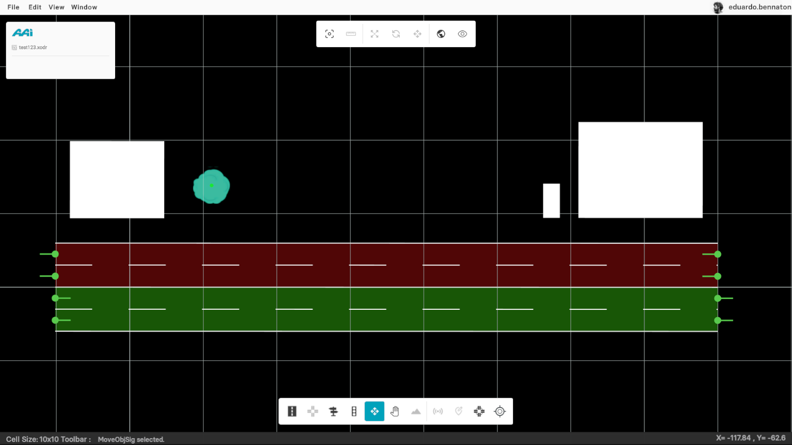
1. Click and hold the secondary mouse button (usually the right button).
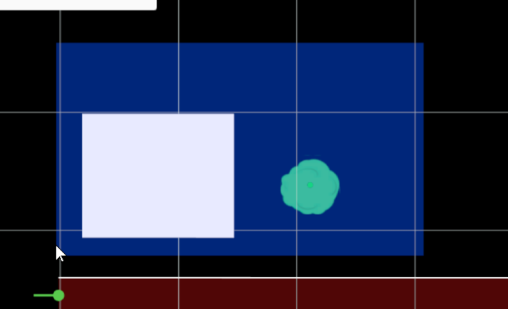
2. With the secondary mouse button on hold, drag the objects / signals to the new location and let go of the mouse.
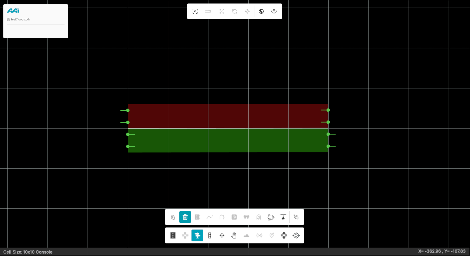
Pan
This option allows the user to navigate the map-editing window in a view-only mode—enabling panning without making any edits
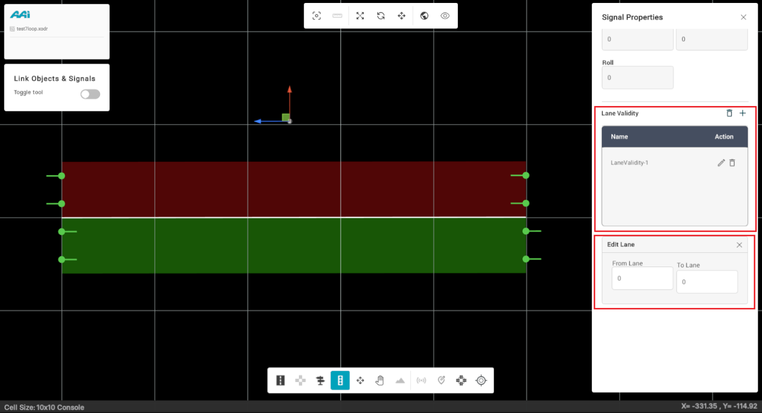
Lane Validity
By default, objects are valid for all lanes pointing into the object’s direction. Once you have added object/objects on a road, you can specify their validity on the limited lanes. For instance, there are multiple lanes in a road, and you want to limit the existing object on a road to only few lanes.
Note: For single-lane-validity of the signal, provide identical values for fromLane and toLane.
2. Select the "Add" button (or the "+" icon).
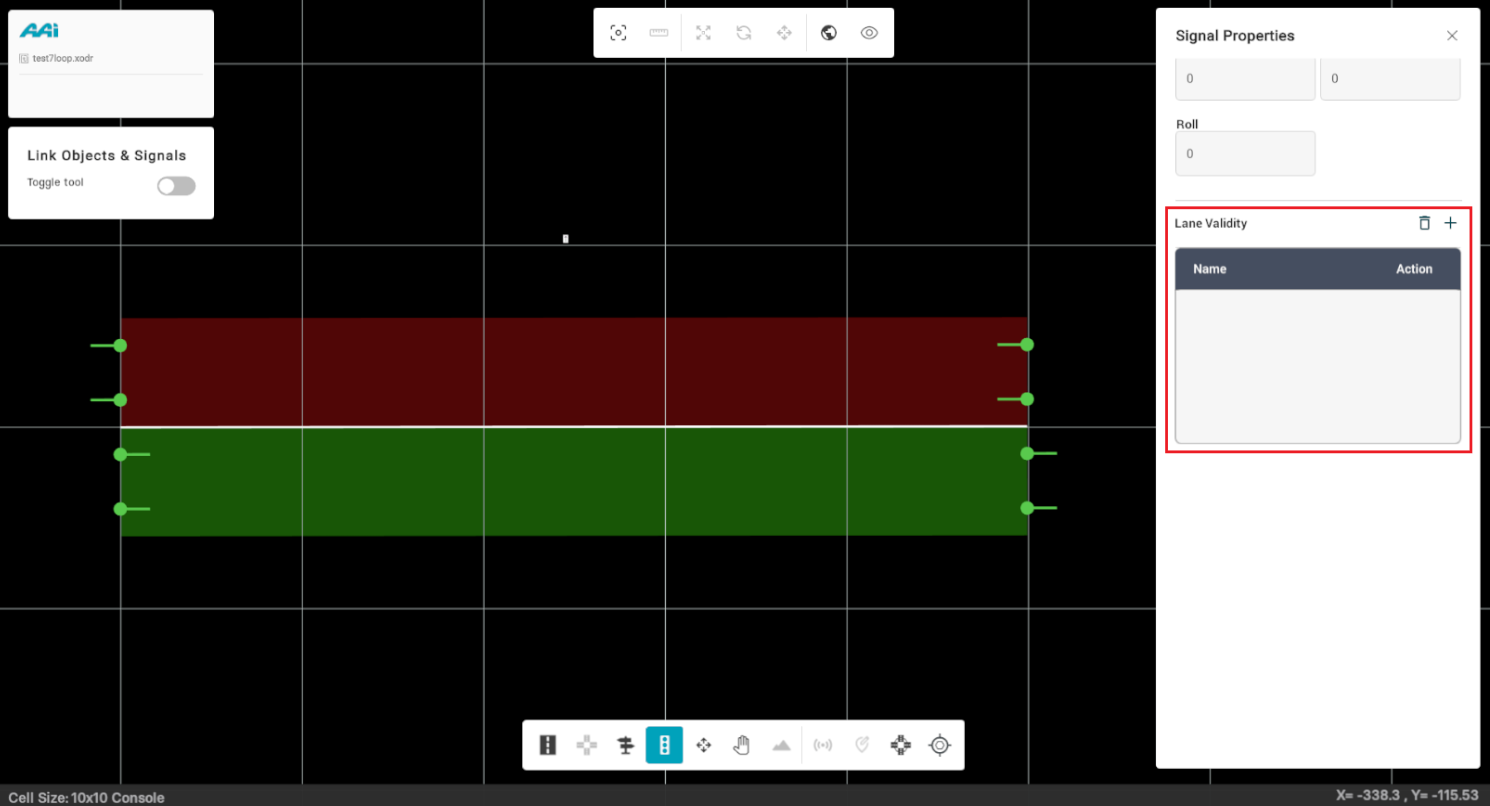
In From Lane, enter the Lane Position of the starting lane and in toLane entry box, type the Lane Position of the last lane for lane validity.
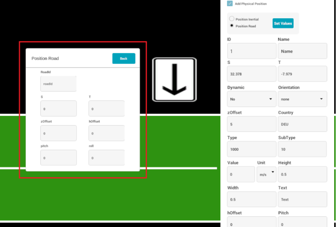
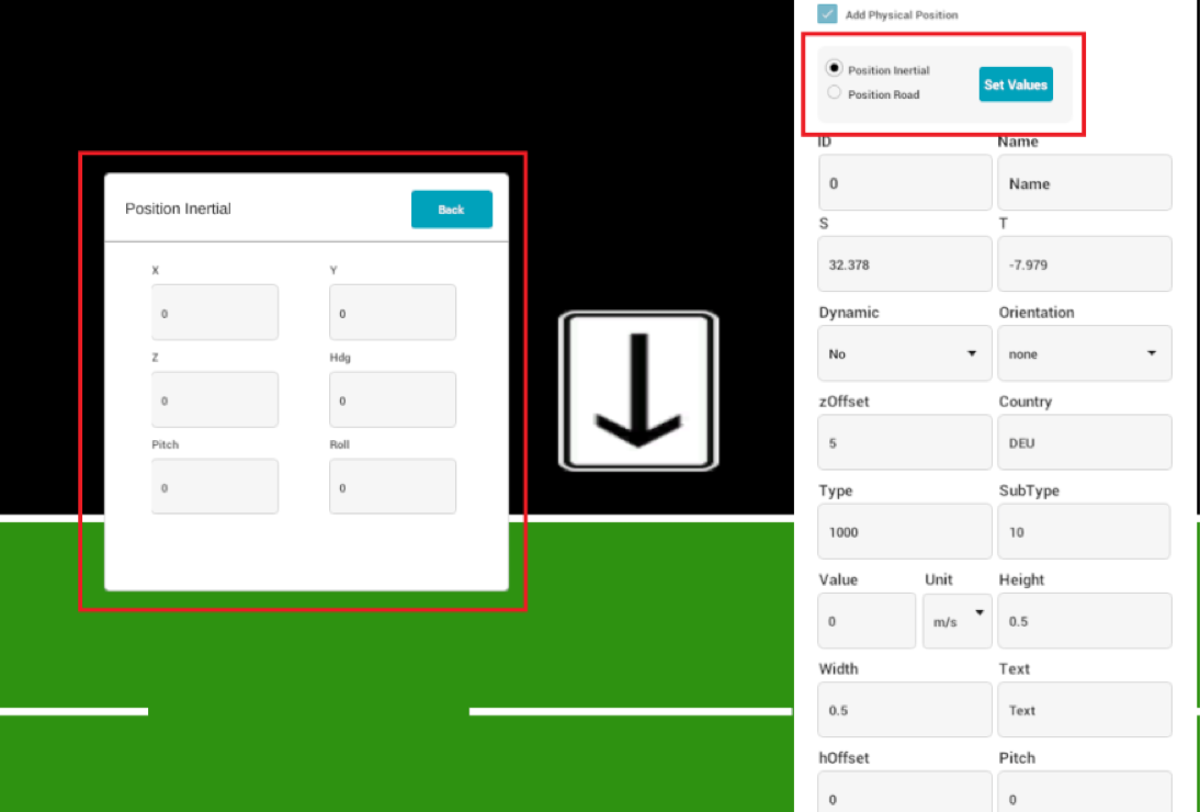
Position Road
This option lets you relocate the physical position of the existing signal. Note that the logical position of the signal remains the same.
position inertial, needs x, y and z coordinates of the new location of the signal.
Add a signal if you currently have none. Locate and click the signal without having any tool selected.
From the signal properties panel, select "Add Physical Position". This will appear at the very top of the signal properties panel, so make sure you scroll up if needed.
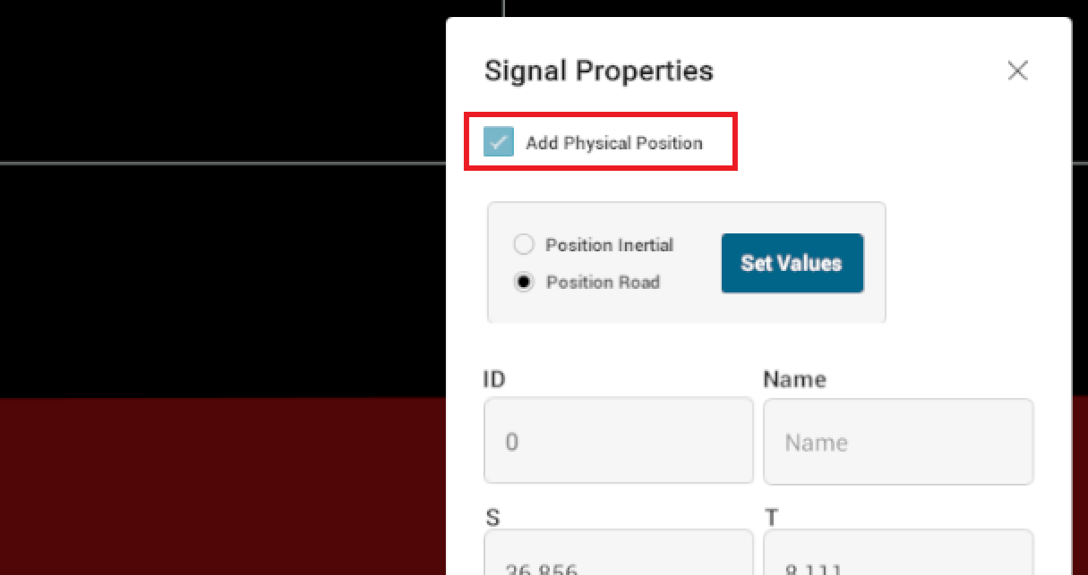
When the checkbox is enabled, some new variables will show up on a new popup.
Make sure to select "Position inertial". This will modify the variables inside of the popup. Adjust the needed x, y and z coordinates of the new location of the signal.
Transform Ego
Information is currently unavailable in the latest RepliMap version.
Tram Powerlines
This tool enables users to create and link connectors within the map-editing view, supporting multiple connection configurations. It is designed to realistically depict wire-based connections—such as power lines—between poles, connectors, and the dependent tram feature itself.
1. Navigate to the "Tram Powerline" tool located in the "Road" section.
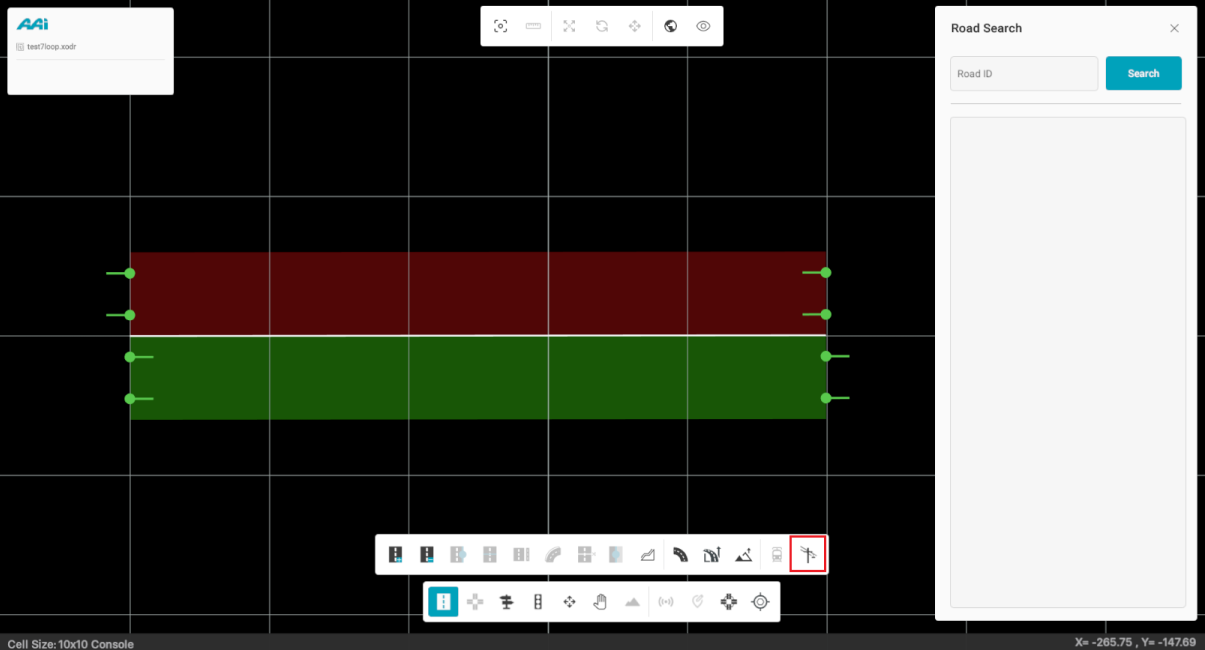
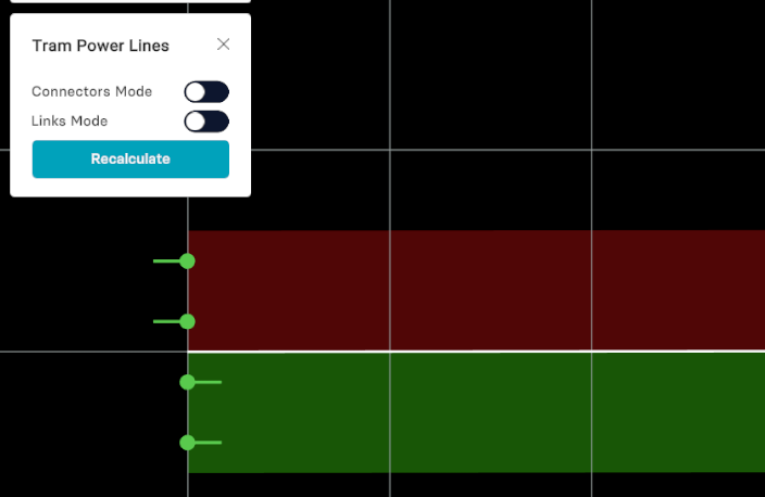
2. Once selected, a panel titled "Tram Power Lines" will open, displaying two modes:
- Connectors Mode: Connectors Mode allows you to place connectors where needed.
- Link Mode: enables the user to create connections between connectors and the dependent tram (if enabled).
Connectors Mode
This feature allows users to place connectors as needed for tram powerline configurations. Connectors serve as attachment points for either poles or dependent trams and can be placed freely anywhere on the map, independent of road positions.
Creating Connectors
1. Toggle the "Connectors Mode" switch. When enabled, it will turn cyan.
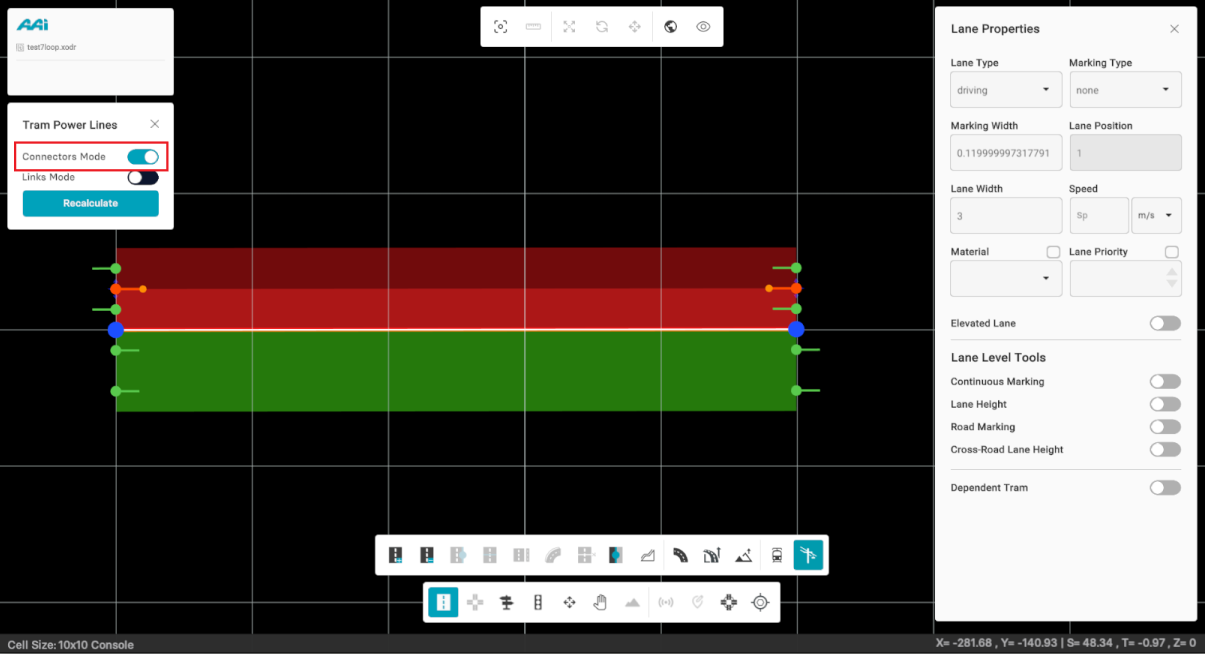
2. Use the primary mouse button (typically the left button) and click on the desired locations where you want to place connector points.

Deleting Connectors
1. Toggle the "Connectors Mode" switch. When enabled, it will turn cyan.
2. Use the secondary mouse button (typically the right button) and click on the desired locations where the place connector points are.
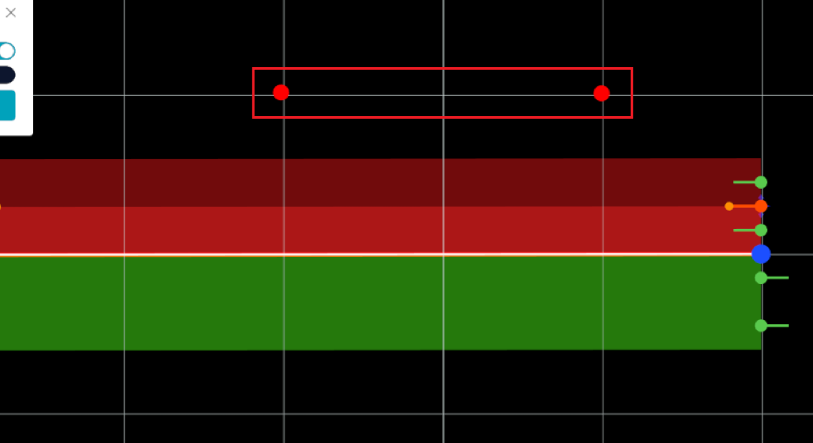
Connectors can also be placed directly on a dependent tram track within a lane. When placed, they appear as a green sphere, vertically centered along the lane. These connectors can also be used in the linkage process.
Links Mode
This feature allows users to create links for tram powerline configurations. Links act as connection lines between poles, dependent trams, or connectors, and can be freely established anywhere on the map where these elements are present.
Creating Links
1. Toggle the "Links Mode" switch. When enabled, it will turn cyan.
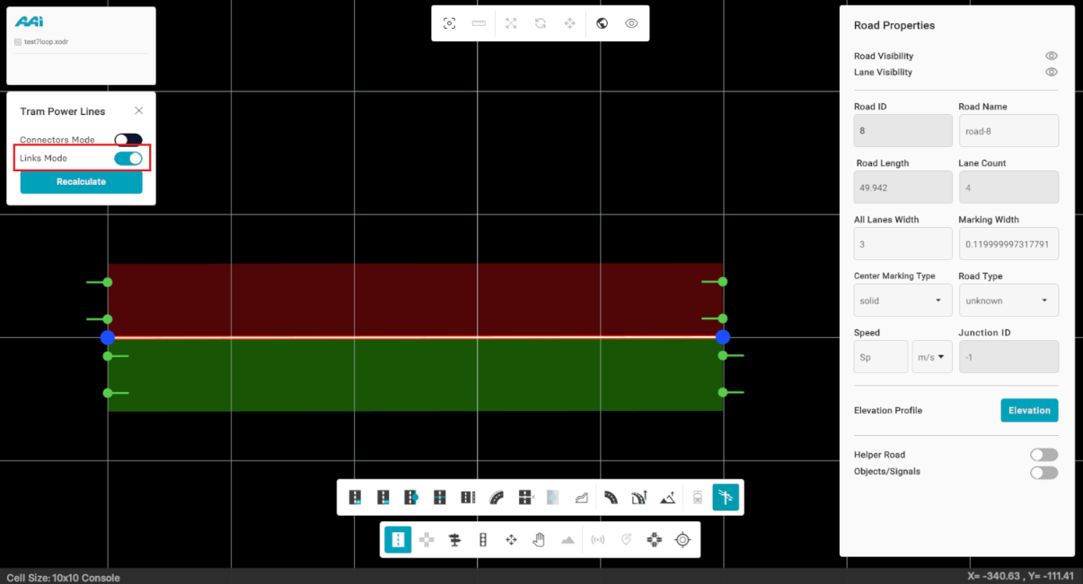
2. Use the primary mouse button (typically the left button) to click on the desired location for the first connector. Then, click again on the second location to place the second connector. If done correctly, a connection will be created between the two points.

Deleting Links
1. Toggle the "Links Mode" switch. When enabled, it will turn cyan.
2. Use the secondary mouse button (typically the right button) and click on the link.

Links can also be made directly on with dependent tram track connectors.

Delete Obj/Sig
Enables users to delete objects directly, bypassing the need to manually select each item and use the standard deletion shortcut. This streamlines the process for quicker, more efficient object removal.
1. Select the "Repeat" sub-tool inside of the "Objects" tool.
2. Click on the object/signal that you wish to remove.
Repeat Tool
The Repeat Tool in RepliMap allows users to automatically place multiple static scene objects — such as trees, poles, or other environment assets — along a selected road.
It is designed to simplify the process of adding repeated objects along lanes or map edges, supporting both Discrete and Continuous placement modes.
To begin, first select the Repeat tool from the Object Toolbar. This will open the Add Objects Along the Road panel on the right-hand side of the editor.
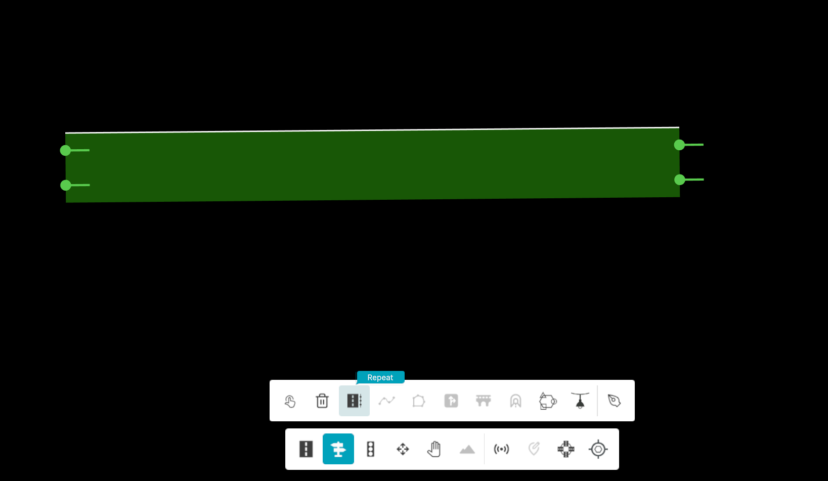
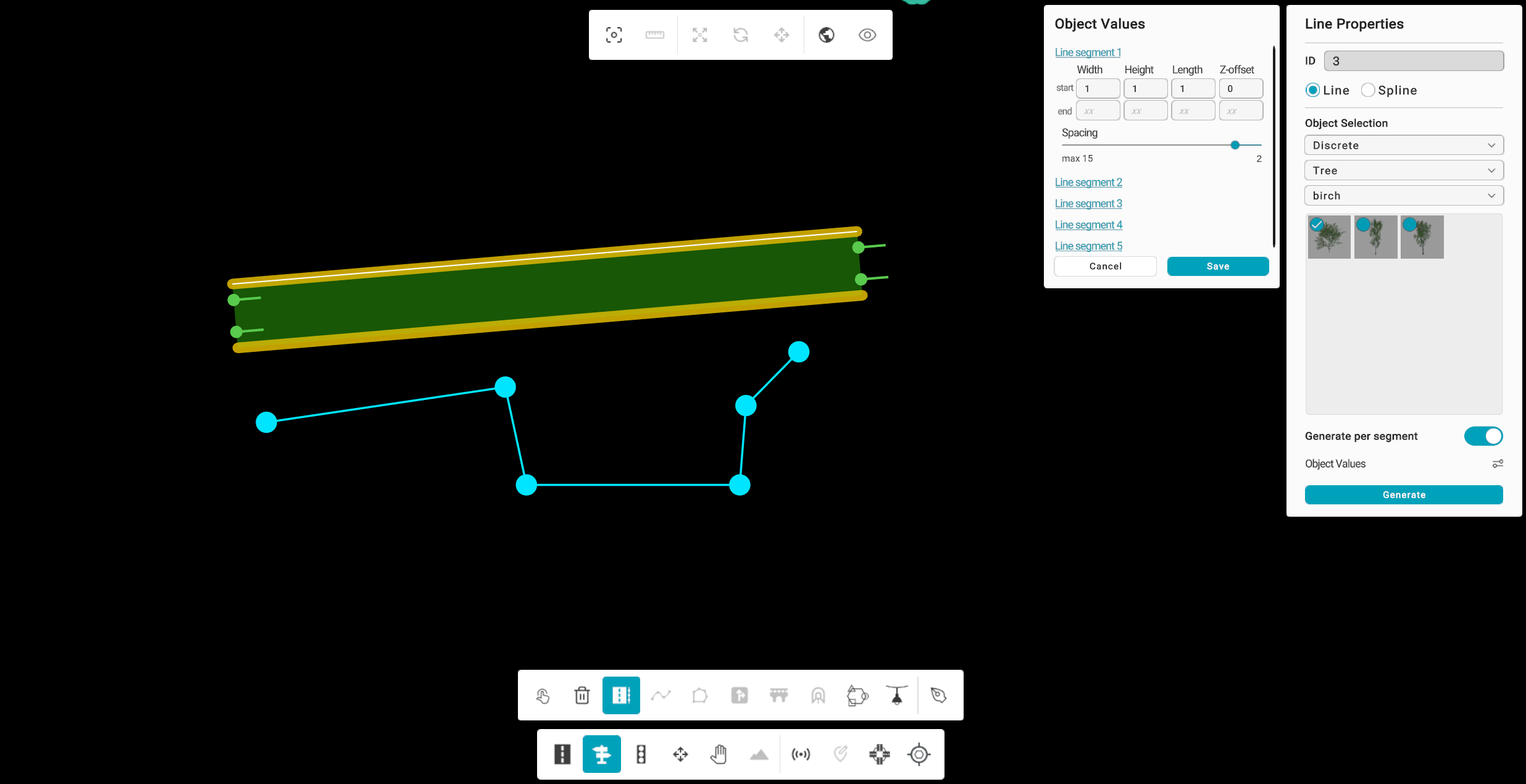
Once the tool is active, left-click on a road to select it. Then, click along the lane to create multiple anchor points that define your desired placement path. Each point represents a segment for object placement. When you have placed the desired anchors, press Enter to complete the line — the line will appear in cyan, indicating it is ready for configuration.
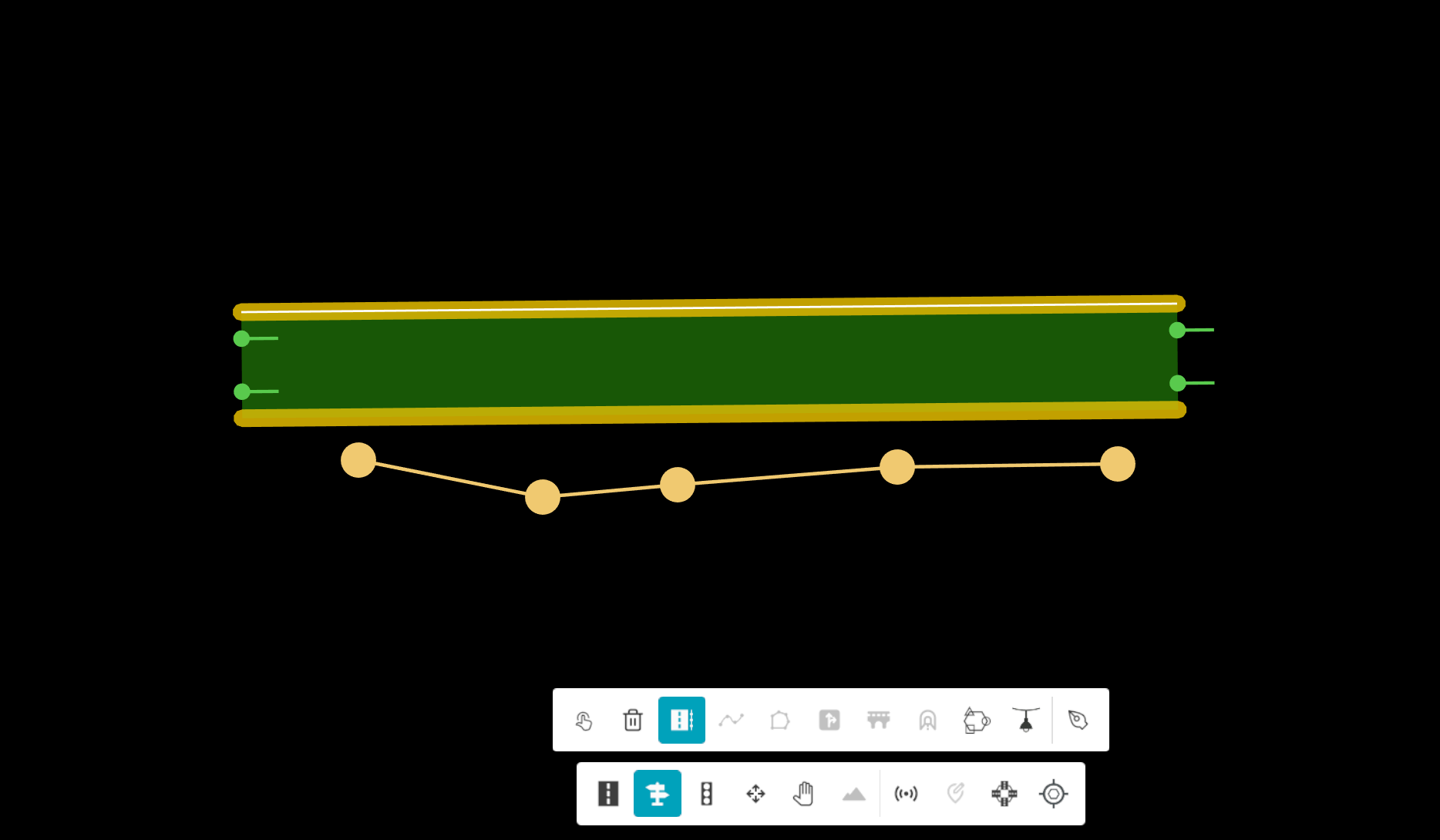
After completing the line, the Repeat Properties panel appears automatically. Here, you can select how the objects should be placed along the line — choosing between Discrete or Continuous mode, and defining the specific object type and subtype to use.
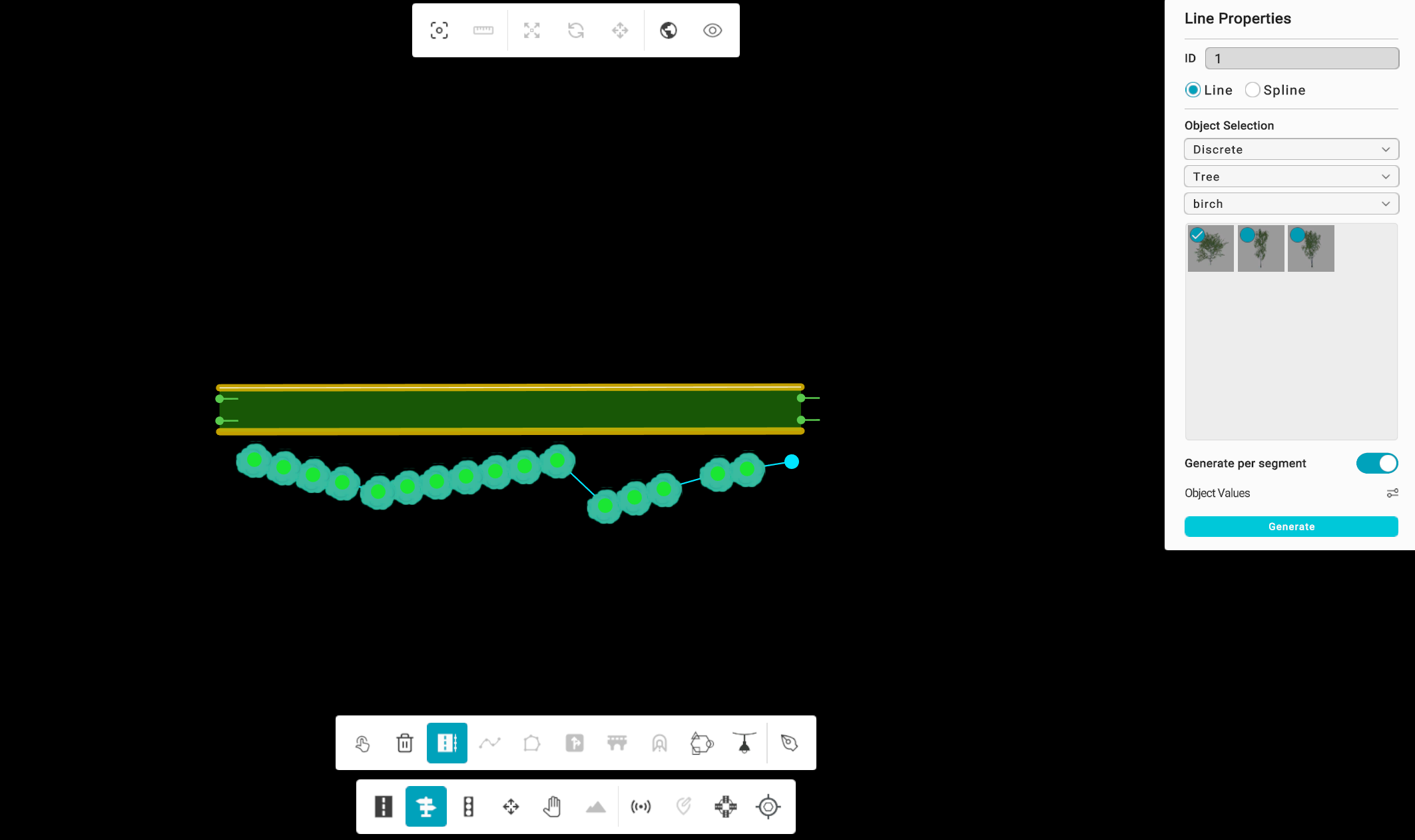
Line Mode
In Line Mode, RepliMap connects the placed anchor points with straight line segments. This mode is useful for uniform, straight-road sections and supports both Discrete and Continuous placement.
- Discrete: Objects are placed at defined spacing intervals along the line.
- Continuous: Objects are placed seamlessly along the path without gaps.
- Per Segment: Allows you to apply individual spacing, size, or height values for each segment independently.
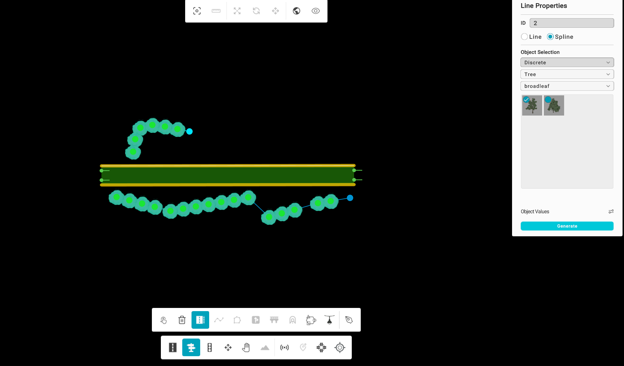
Spline Mode
In Spline Mode, the tool connects the anchors with a smooth curve, ideal for curved or organic road shapes.
Spline Mode automatically switches to Discrete placement, since Continuous placement is not supported for splines. All size and spacing parameters are applied globally along the spline.
Once parameters are adjusted, click Generate to apply and visualize the repeated objects along the curved line.
Adjusting Object Values
After drawing your repeat line, open the Object Values Panel to customize your object parameters. You can modify:
- Width or Radius
- Height
- Length (Start and End)
- Z Offset
- Spacing
Once your parameters are set, click Save to confirm the changes, and then click Generate to place the objects along your defined path.
Editing and Deleting Lines
You can easily modify or remove the repeat line after it’s created:
- Move a point: Drag the anchor node to reposition it.
- Delete a point: Select the node and press Delete.
- Delete full line: Use the Delete Line option to remove both the line and the placed objects.
If fewer than two anchors remain, all generated objects for that line are automatically removed.
Notes and Best Practices
- Press Esc to cancel line drawing before completing it.
- The cyan line color indicates the currently active Repeat line.
- Always click Save before Generate when changing object parameters.
- Use Line Mode for straight alignments and Spline Mode for curved ones.
- Switching between Line and Spline will reset the current placed objects (a confirmation prompt will appear).
- Ensure the selected road is highlighted before starting — the Repeat Tool only works when a valid road segment is active.
This tool is designed to simplify the process of adding repetitive static assets to your simulation map — enhancing efficiency, reducing manual work, and maintaining consistency in map design.
Area
Feature is currently unavailable in the latest RepliMap version.
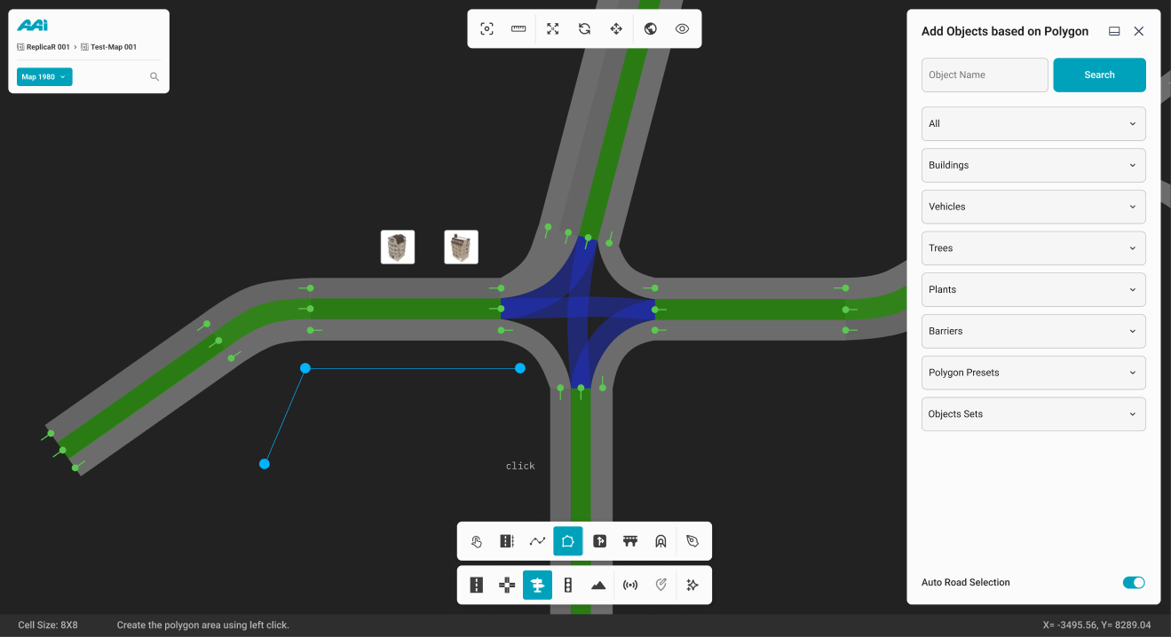
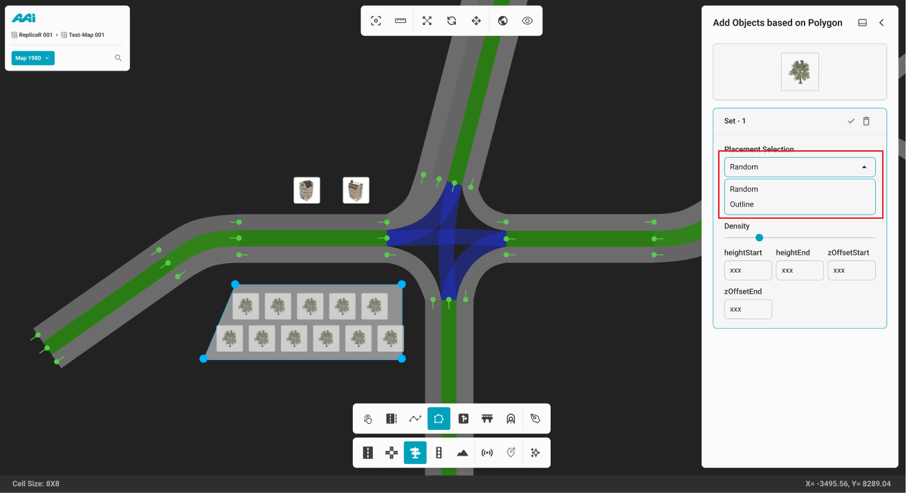
Enables users to define an area using a polygon-based placement method, allowing multiple objects to be traced and placed simultaneously—eliminating the need to manually place each object individually within the selected area.
1. Select the "Area" sub-tool inside of the "Objects" tool. This will open the "Add objects along the Polygon" panel. Use the primary (usually left) mouse button click to place the first point of the polygon.

2. Continue placing points along the desired area until the polygon shape is fully closed.
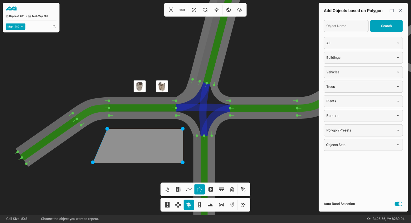
3. Once the polygon is closed, drag and drop the desired object into the polygon area.
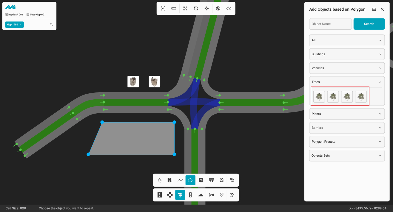
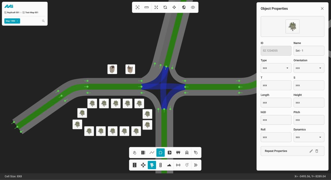
4. Upon completion, the Object Polygon Properties panel will open, allowing the user to further customize the polygon’s attributes as needed.

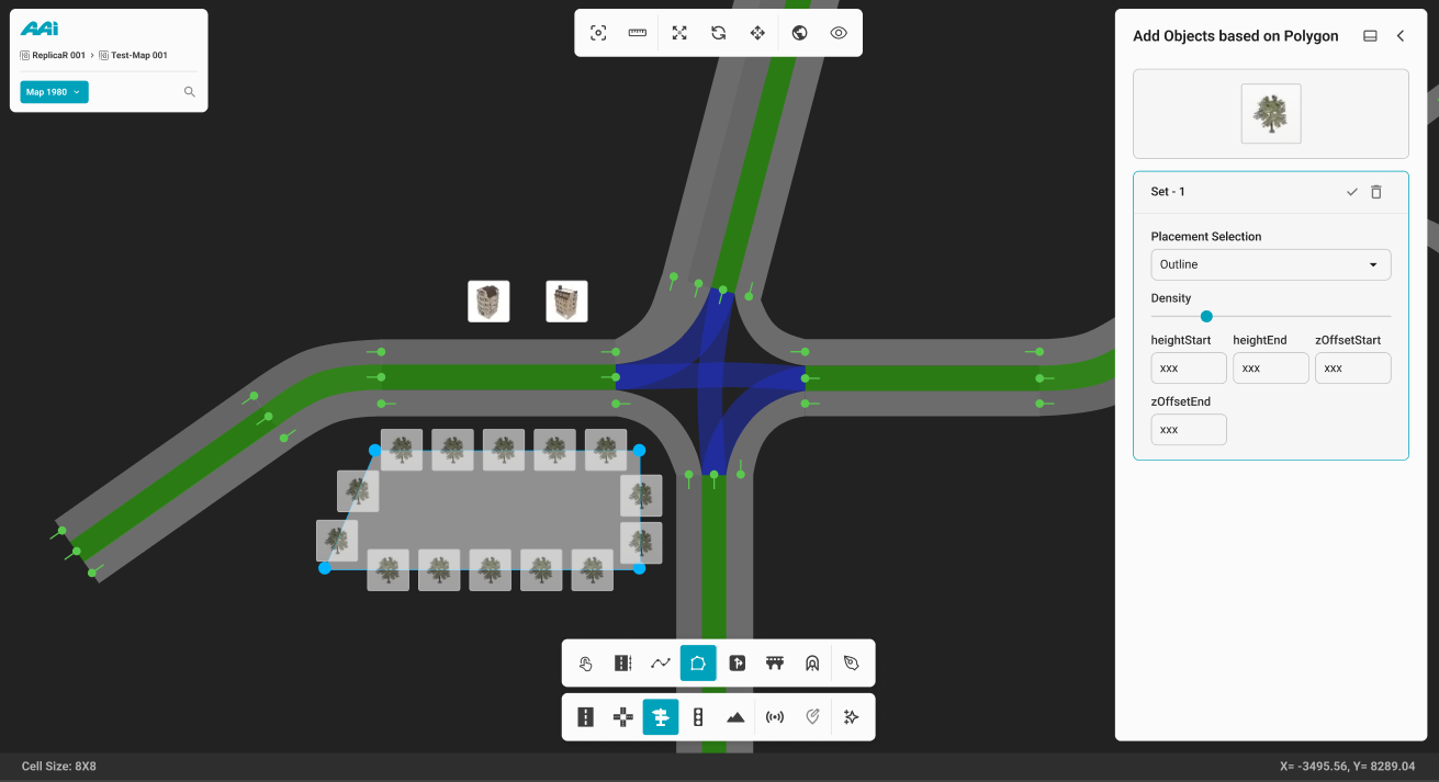
5. To define the overall placement pattern within the object polygon area, click the "Placement Selection" dropdown.
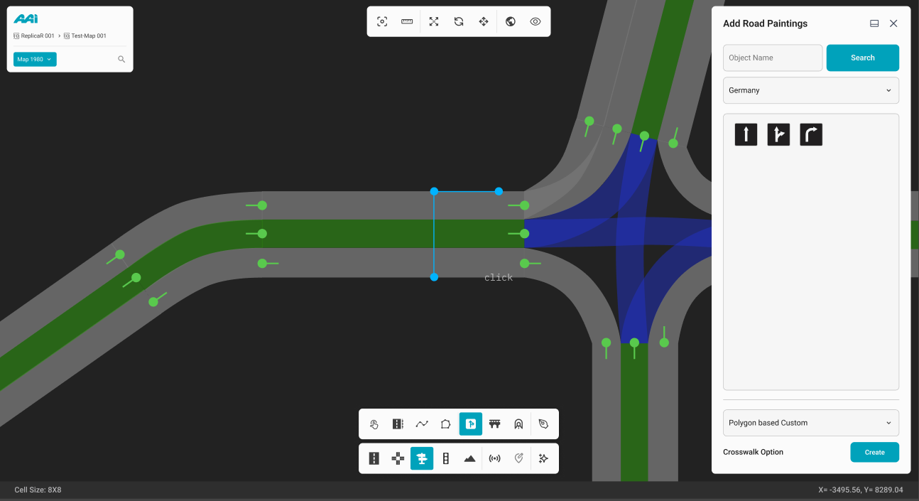
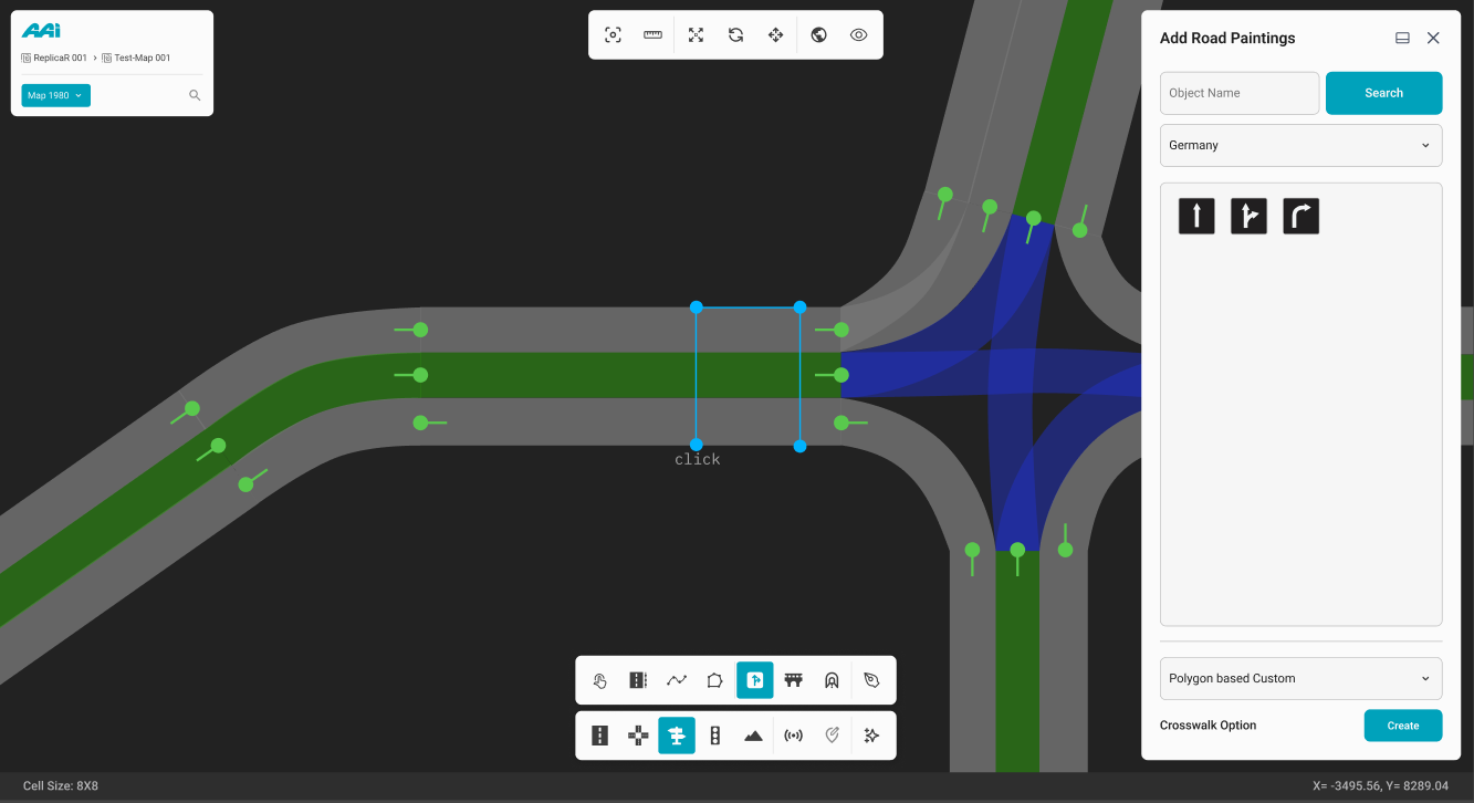
Road Painting
Feature is currently unavailable in the latest RepliMap version.
Enables users to apply road markings based on country-specific sign standards for a more accurate representation of the selected location. This tool also allows for detailed customization of individual road markings to suit specific design requirements.
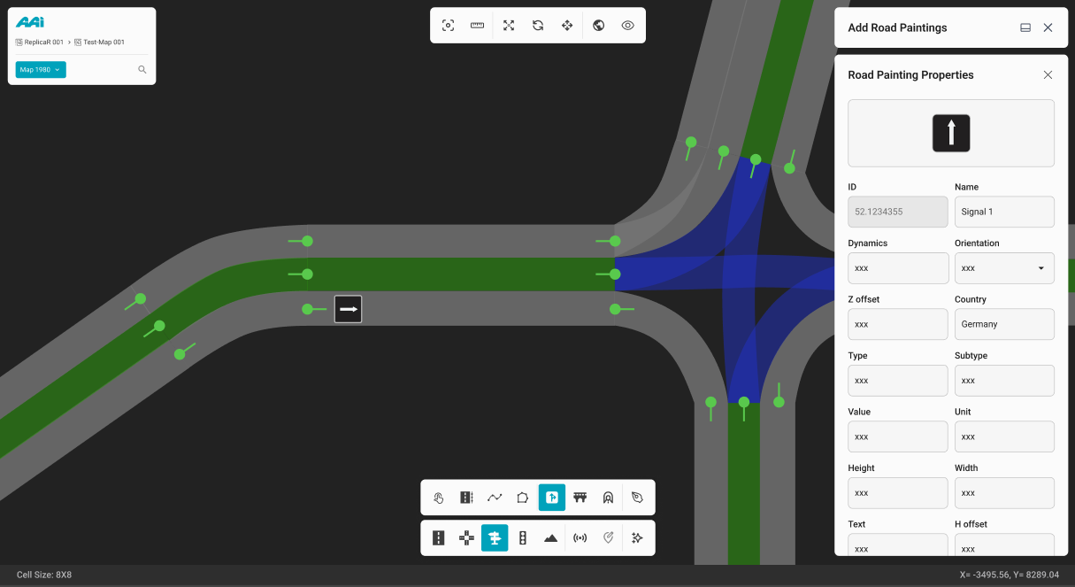
1. Select the "Road Painting" sub-tool inside of the "Objects" tool. Click the primary-mouse button (usually left) within a particular road.
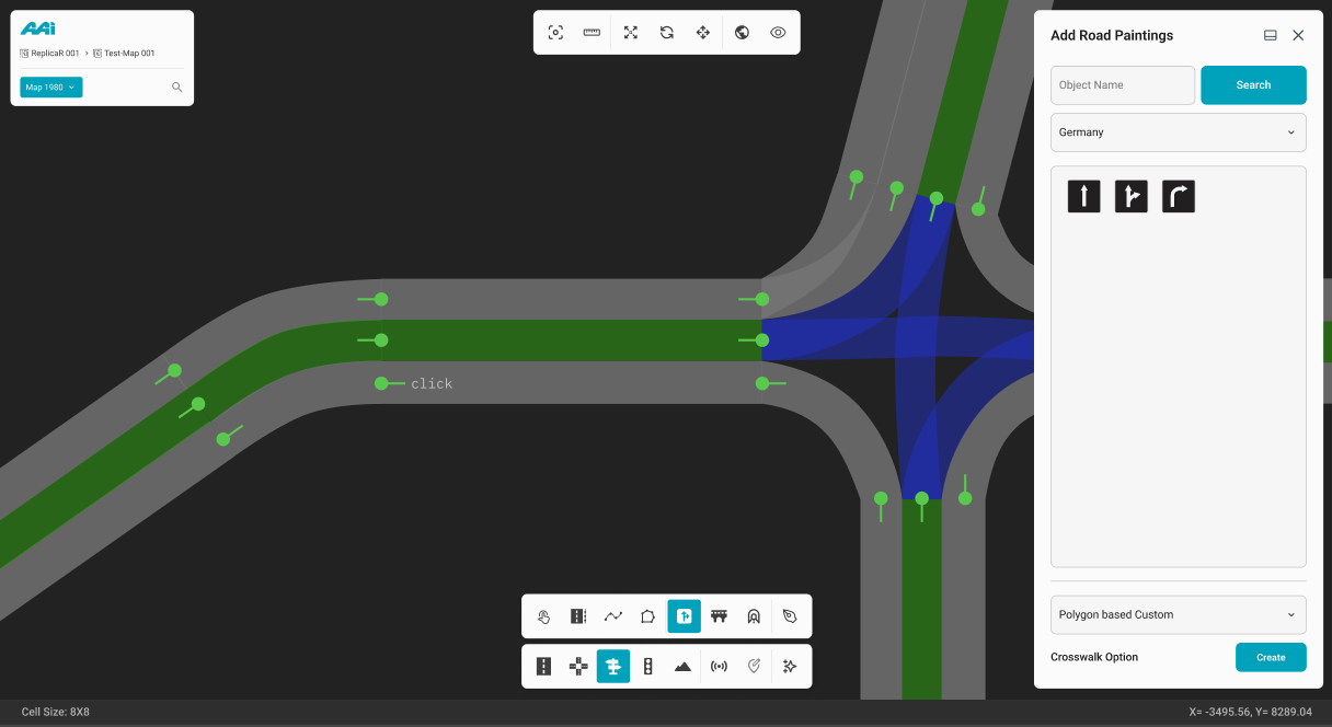
2. This action places the road painting at the clicked position on the designated road and simultaneously opens the Road Painting Properties panel for further customization.
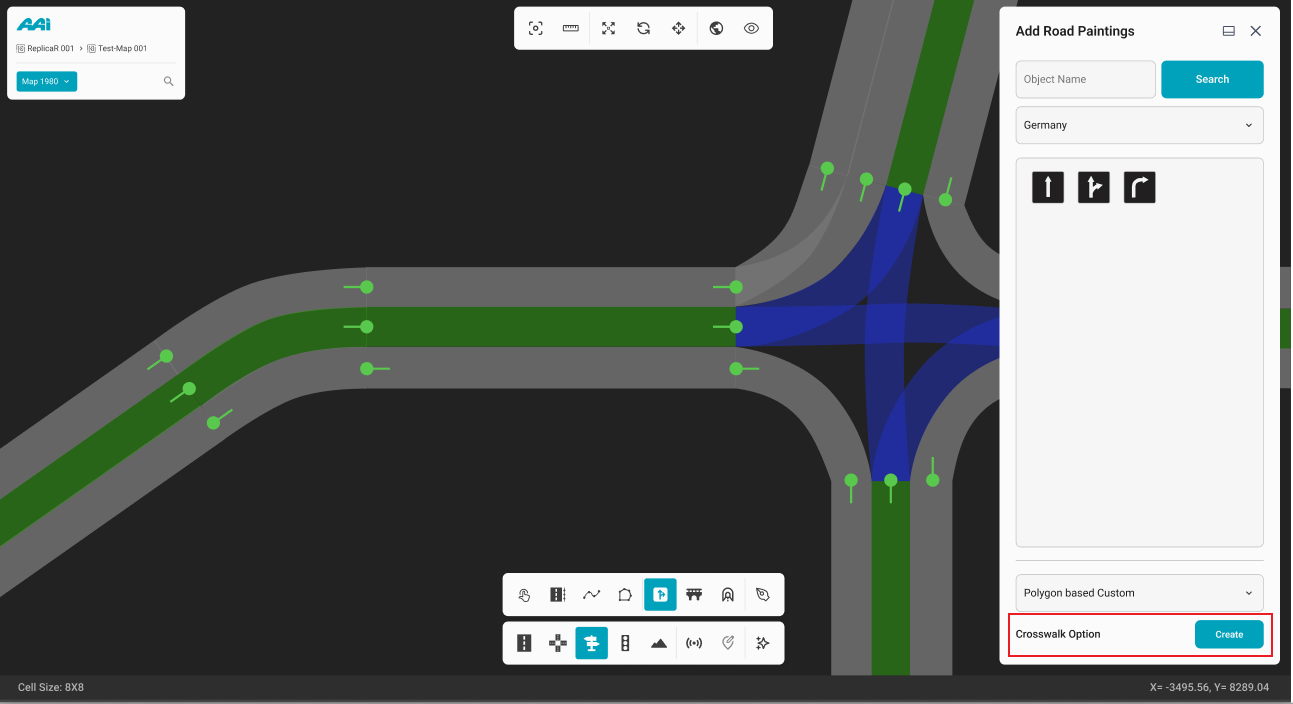
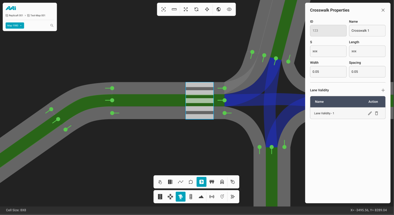
Crosswalk Option
1. Select the "Create" button for the Crosswalk Option within the Add Road Paintings panel.
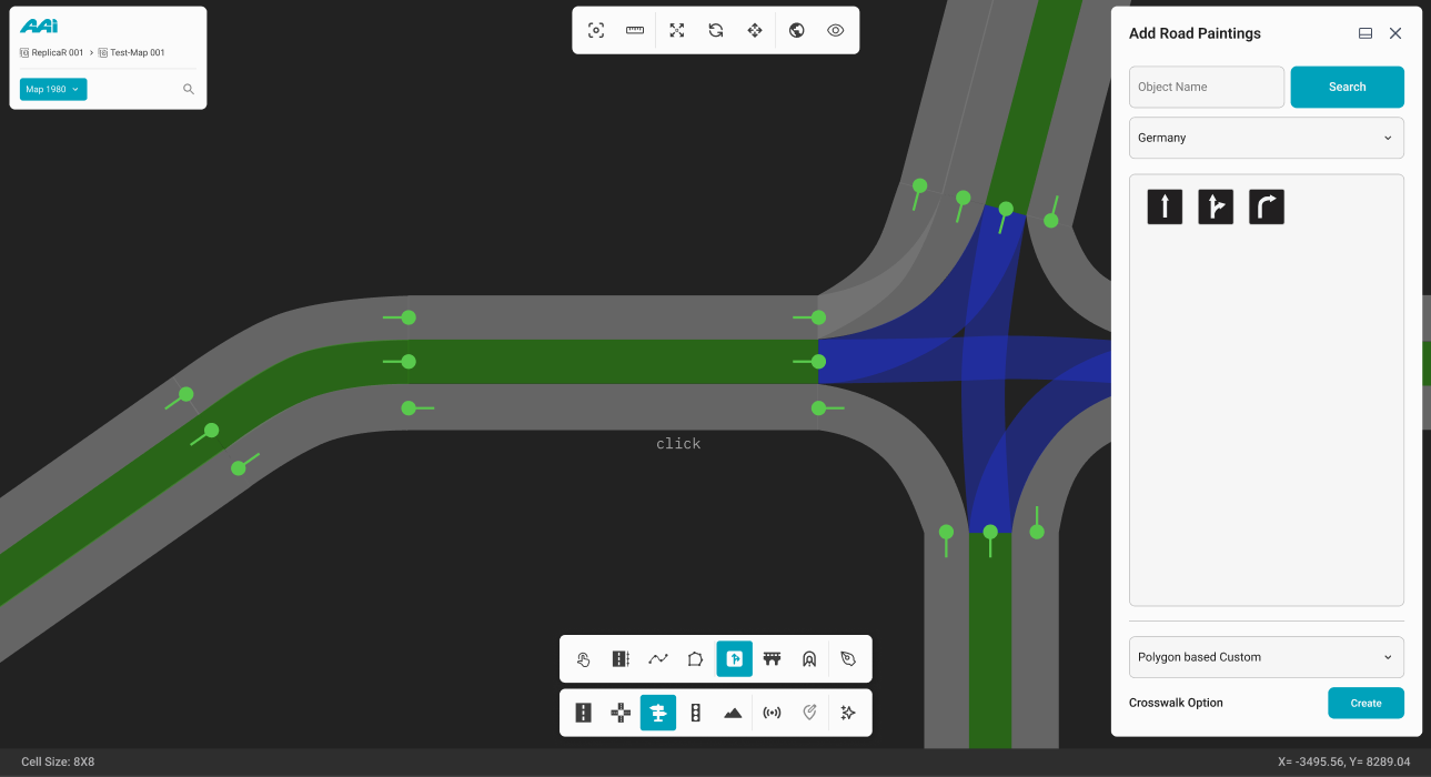
2. Click the primary-mouse button (usually left) within a particular road.
3. Click the primary-mouse button (usually left) again within a particular road to set the end of the crosswalk.
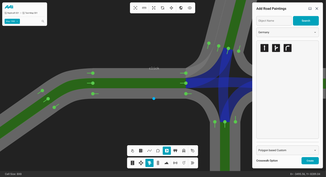

4. Now, repeat this process until the crosswalk anchors outline the entire area of the desired crosswalk.
Once completed, the "Crosswalk Properties" panel will appear, allowing the user to further customize the crosswalk as needed.
Bridges
Feature is currently unavailable in the latest RepliMap version.
1. Select the "Bridge" sub-tool inside of the "Objects" tool. Click the primary-mouse button (usually left) within the RepliMap window to set the initial coordinates of the tunnel.
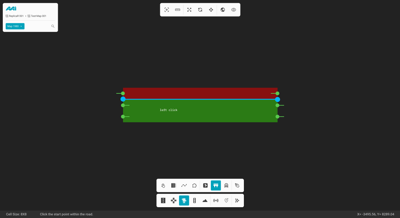
2. Press the primary-mouse button (usually left) at a different position at the end of the road.
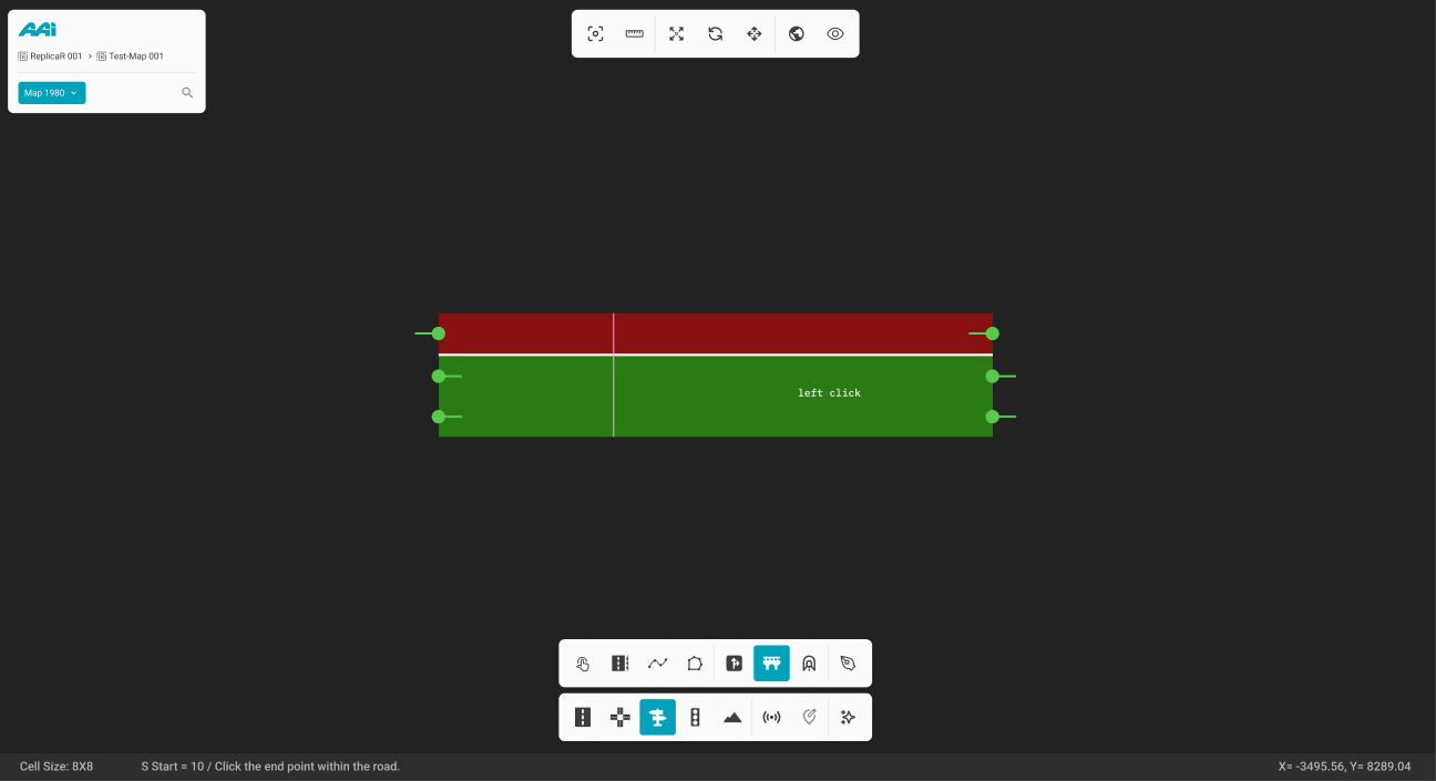
3. This will create the bridge space. Primary (usualy left) mouse click on the bridge space to select the specific bridge.

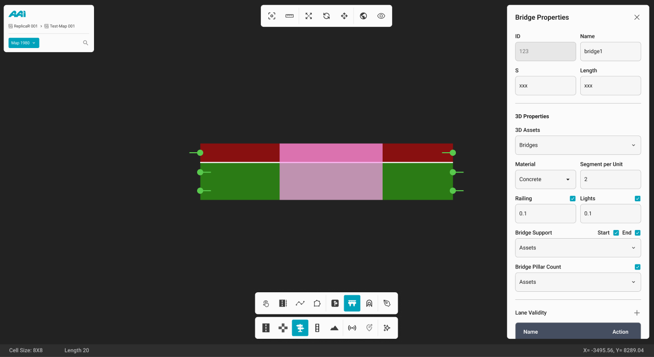
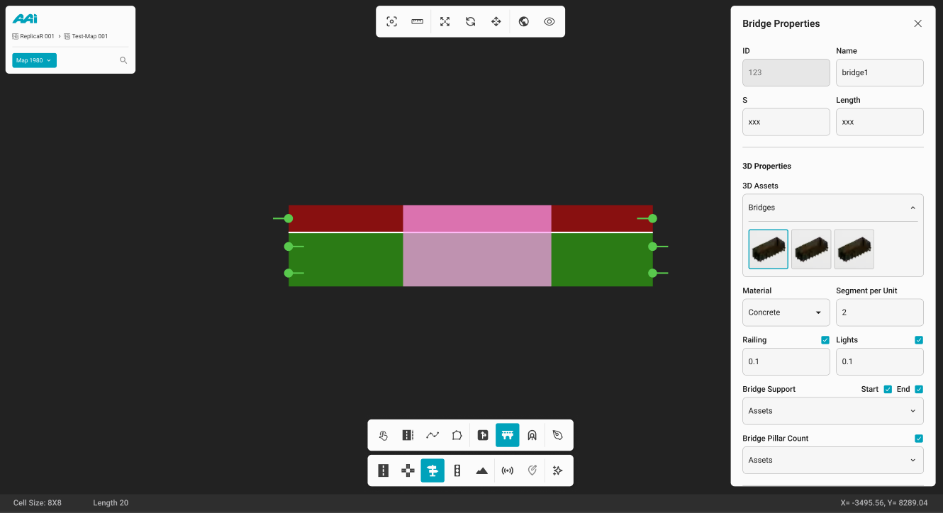
This will open the "Bridge Properties" panel, allowing you to further customize the bridge's attributes to meet specific requirements.
Tunnels
Feature is currently unavailable in the latest RepliMap version.
1. Select the "Tunnel" sub-tool inside of the "Objects" tool. Click the primary-mouse button (usually left) within the RepliMap window to set the initial coordinates of the tunnel.
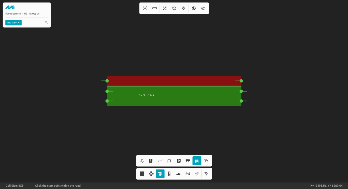
2. Press the primary-mouse button (usually left) at a different position at the end of the road.
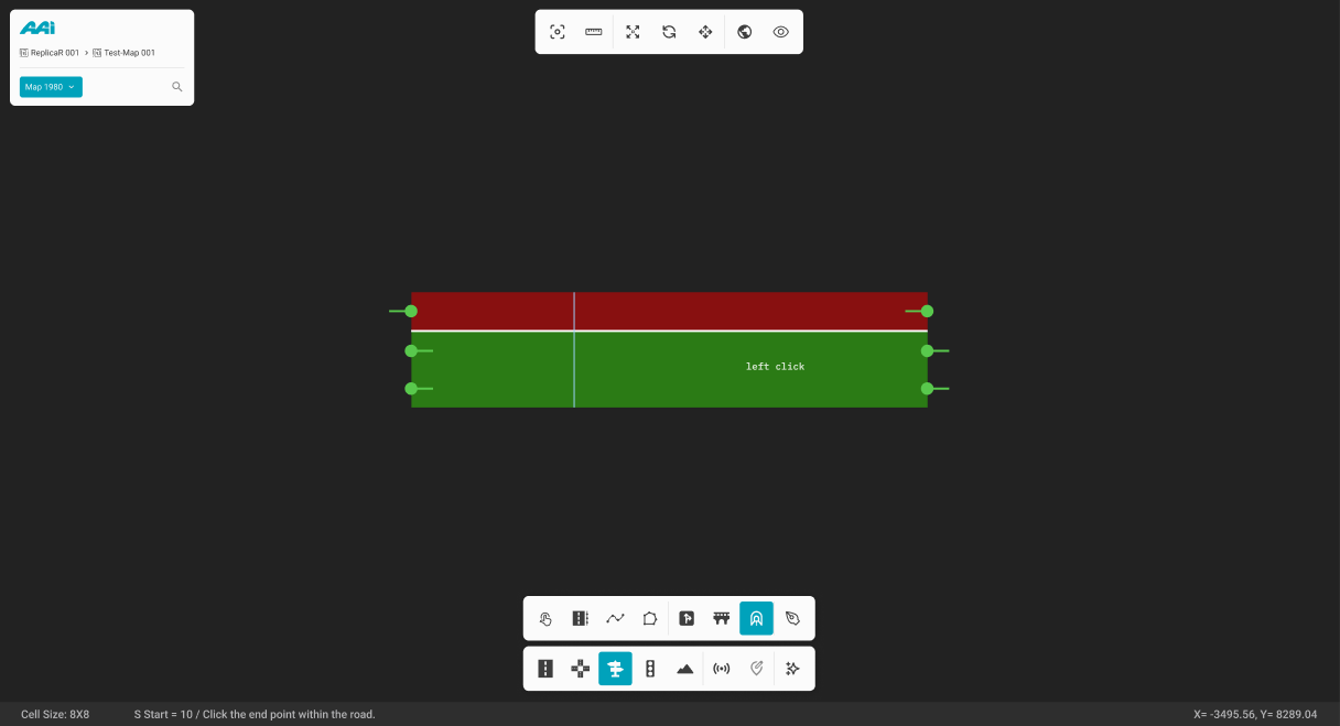
3. This will create the tunnel space. Primary (usualy left) mouse click on the tunnel space to select the specific tunnel.

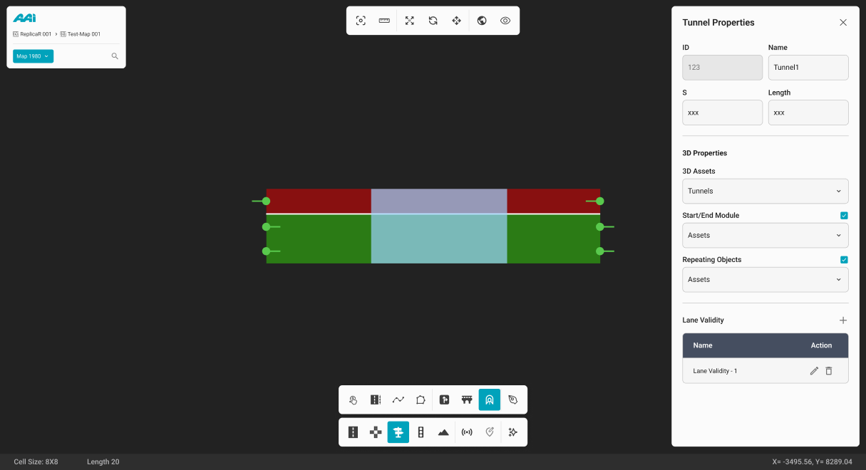
This will open the "Tunnel Properties" panel, allowing you to further customize the tunnel's attributes to meet specific requirements.
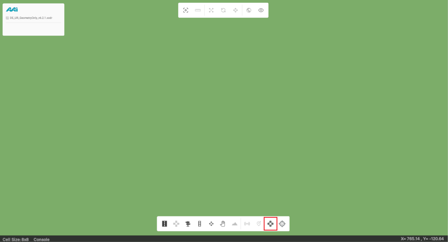
Junction Outline
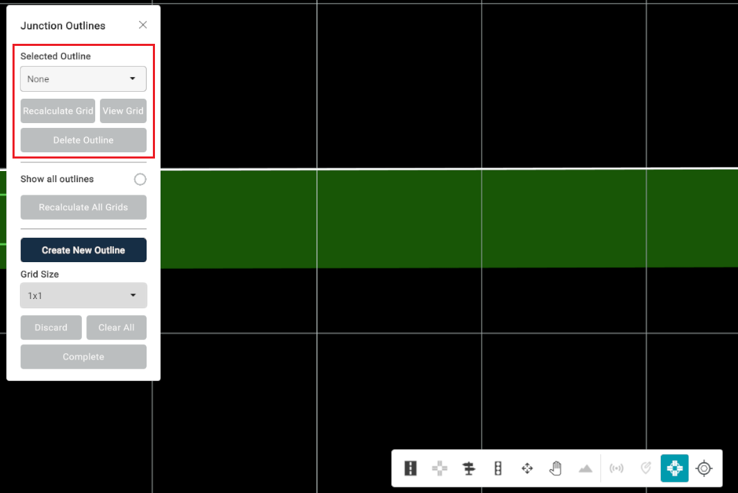
Enables the user to combine multiple junctions into a single group, improving map visuals and offering enhanced functionality for future designations if required. To operate the Junction Outline tool, navigate to the editor bar and select "Junction Outline".
The user will be prompted with a UI panel displaying the tool. The tool includes multiple sections that allow the user to use the tool differently depending on their intended use.
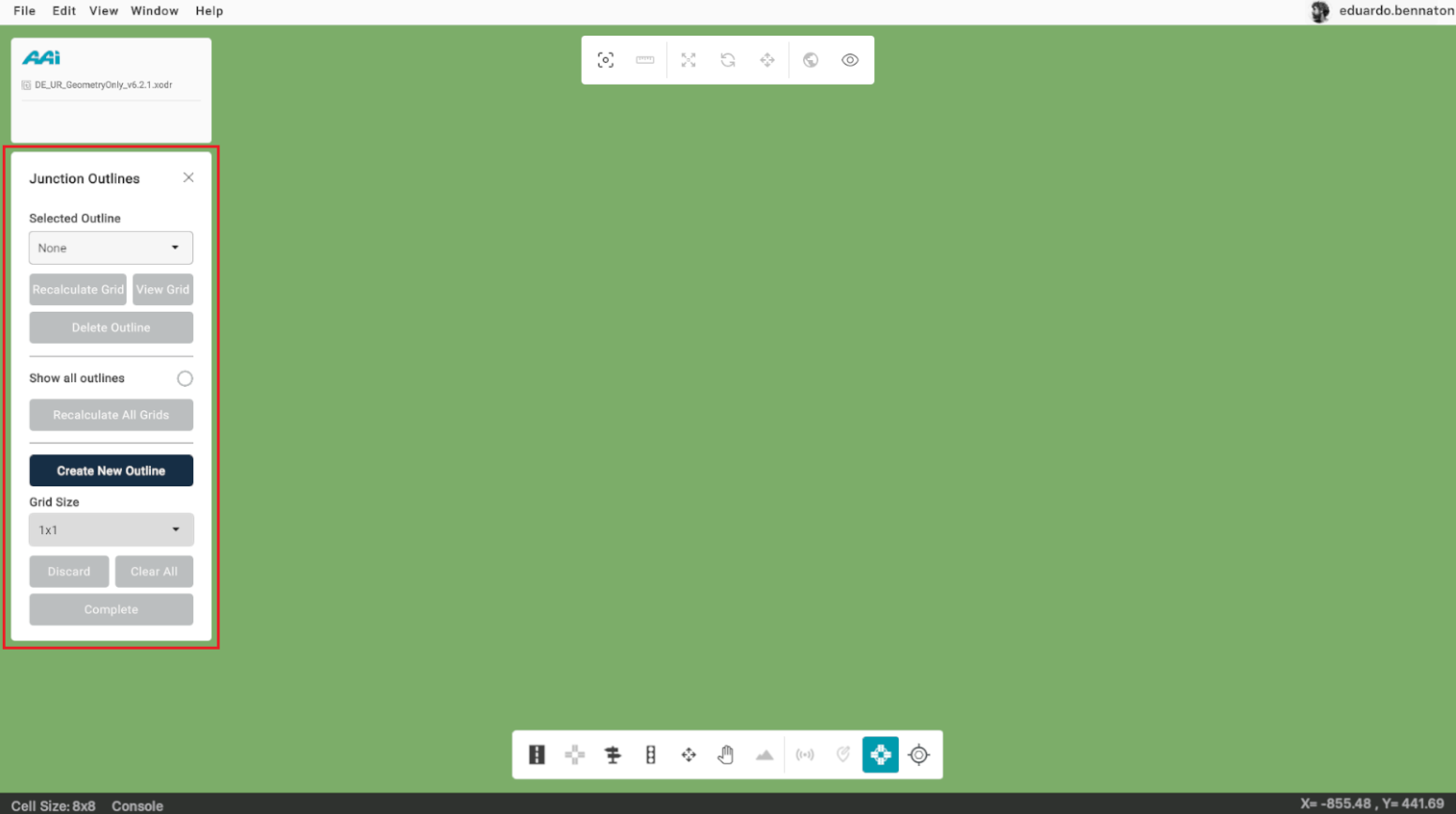
The "Selected Outline" dropdown and section display existing junction outlines. If no junction outlines have been created, it defaults to "None." The "Recalculate Grid" button allows users to recalculate the current grid associated with the selected junction outline. The "View Grid" button visualizes the grid, and the "Delete Outline" button removes the selected grid.
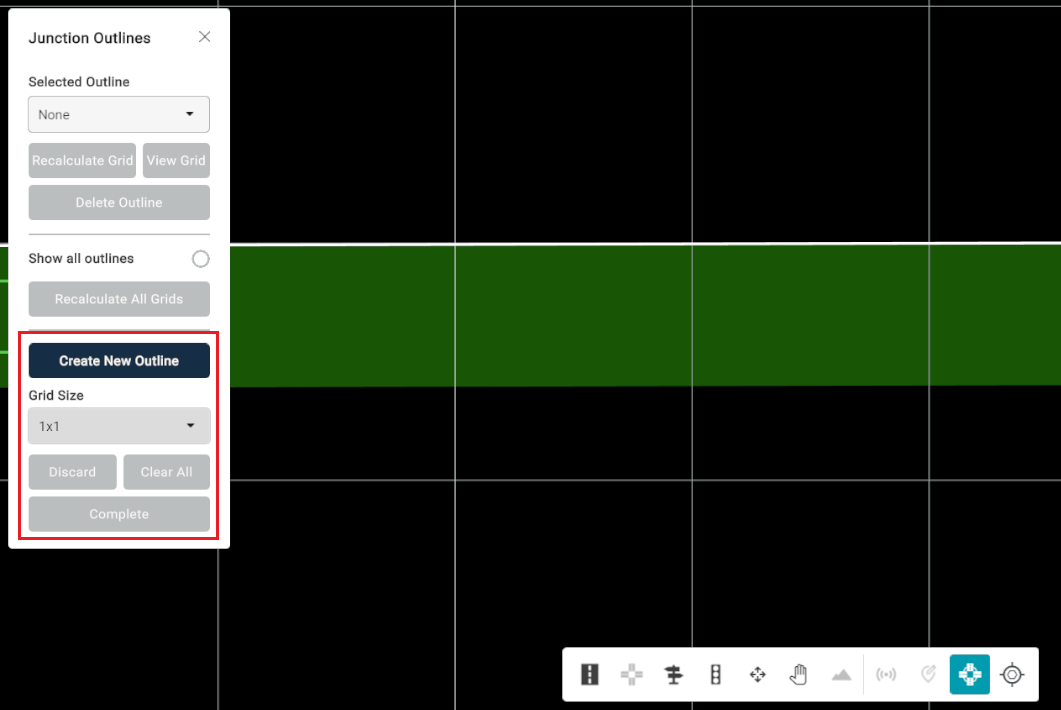
The "Show All Outlines" checkbox displays all existing junction outlines simultaneously. The "Recalculate Grids" button allows users to recalculate the current grids associated with the junction outlines.

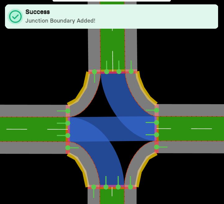
The "Create New Outline" button allows the user to create a custom outline of a junction. This highlighting process (outline creation process) has to be created manually. The user has to:
Guidelines
Navigate to the location where the roads intersect.
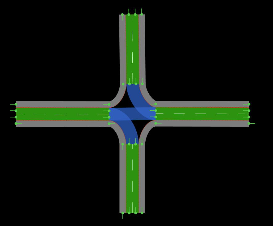
Right-clicking specifies the literal road connection origin, which will turn red. Left-clicking sets an important boundary of the junction outline. With the "Create New Outline" button activated, left-click on the internal sections of the roads, following a counter-clockwise direction.
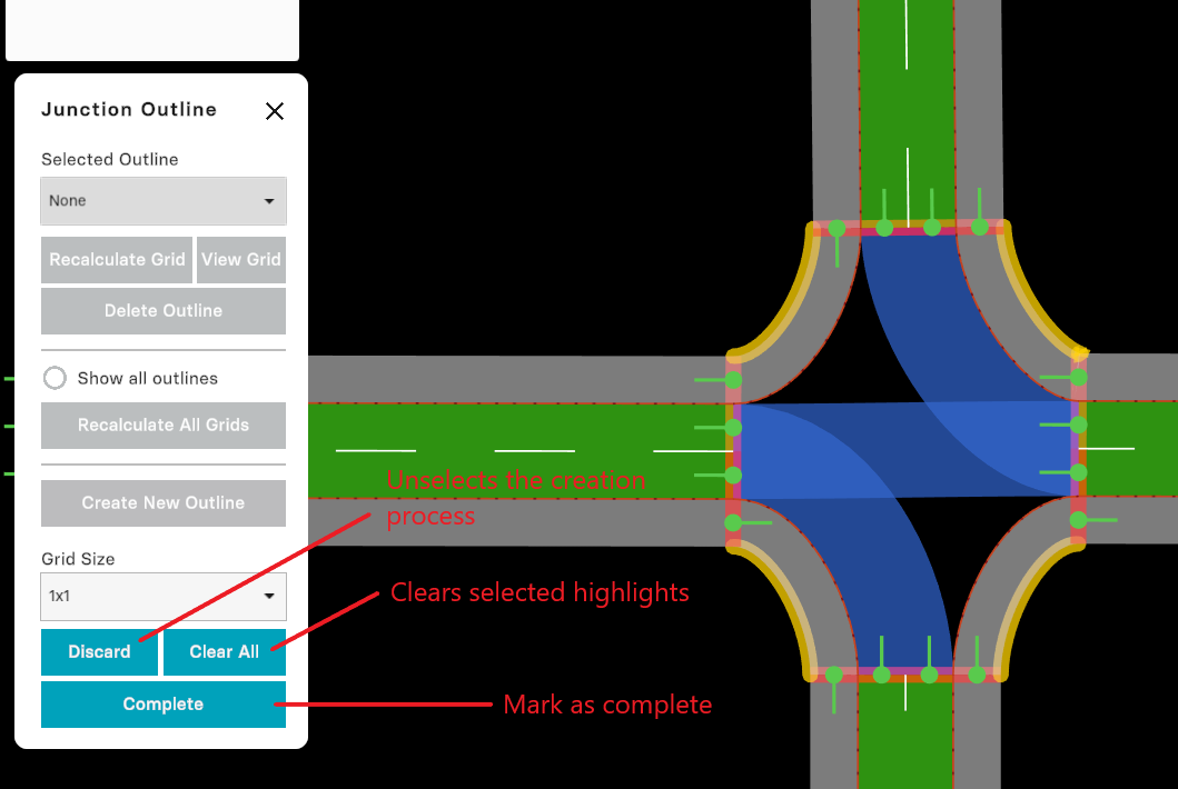
After the junction highlight process is complete, you will visualize the outline in the "Selected Outline" dropdown.
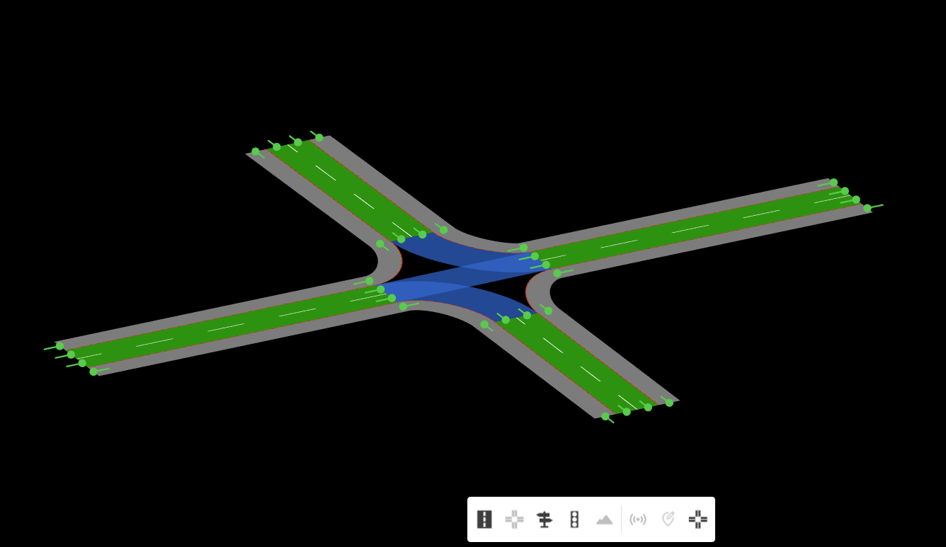
Elevation Tools
Enables the user to define a specific elevation diversity for a given road. These changes can be visualized by holding the "Alt" key and using the mouse (with directional input) to pan seamlessly between 2D and 3D views within the 2D plane. Unlike the View feature in the toolbar, this displays 3D content within the standard 2D visualization.
For this to work, the user must have all tools unequipped. Hold Alt + drag with Mouse Button 1 in the desired panning direction.
Sensor Tool
Feature is currently unavailable in the latest RepliMap version.
Enables users to import sensor data into a visualized map of travel corresponding to the XODR file. Users can retrace the steps recorded in the sensor data, including visual representations of the vehicle, allowing for detailed inspection and analysis.
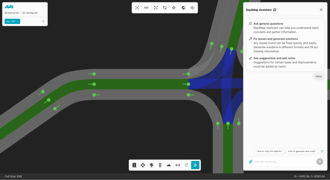
RepliMap Assistant
Feature is currently unavailable in the latest RepliMap version
Provides users with assistance for general questions related to the development of RepliMap. It also helps generate solutions for current issues, such as filling in information and other tasks. Additionally, it suggests improvements and allows users to add notes as needed.
1. Navigate to the "Editor bar" and select the "Assistant" tool.
![]()
2. Once selected, a side panel will appear featuring RepliMap’s AI assistant chat, which can provide information and manage files based on the user's needs.